Electric Circuit Analysis/Kirchhoff's Voltage Law
  |
Circuit Analysis Part II (Laws & Theorems)This part is an introduction to some useful Electric Circuit Laws and theorems. You are encouraged to master the theorems and laws that will be discussed herein as they form a basis upon which most Circuit analysis methods are built. Lesson ReviewWhat you need to remember from Previous Lessons.
Lesson 5: PreviewThis Lesson is about Kirchhoff's Voltage Law. The student/User is expected to understand the following at the end of the lesson.
|
| ||||||||||||||||||||||||||||||||||||||||||||||
Part 1: Kirchhoff's Voltage LawKirchhoff's Voltage Law states:
Notice that a closed circuit path insists that if one circuit element is chosen as a starting point, then one must be able to traverse the circuit elements in that loop and return to the element in the beginning. Mathematically, The Kirchhoff's Voltage Law is given by For reference, this law is sometimes called Kirchhoff's Second Law, Kirchhoff's Loop Rule, and Kirchhoff's Second Rule.
|
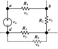
Part 2:Kirchhoff's Voltage Law (Cont...)We observe five voltages in Figure 5.1:
|
Part 3Now, if we take the point d in the image as our reference point and arbitrarily set its voltage to zero, we can observe how the voltage changes as we traverse the circuit clockwise.
Going from point d to point a across the voltage source, we experience a voltage increase of v4 volts (as the symbol for the voltage source in the image indicates that point a is at a positive voltage with respect to point d).
On traveling from point a to point b, we cross a resistor. We see clearly from the diagram that, since there is only a single voltage source, current must flow from it's positive terminal to its negative terminal--clockwise around the circuit path. Thus from Ohm's Law, we observe that the voltage drops from point a to point b across resistor R1.
Likewise, the voltage drops across resistors R2 and R3. Having crossed R2 and R3, we arrive back at point d, where our voltage is zero (just as we defined). So we experienced one increase in voltage and three decreases in voltages as we traversed the circuit.
The implication from Kirchhoff's Voltage Law is that, in a simple circuit with only one voltage source and any number of resistors, the voltage drop across the resistors is equal to the voltage applied by the voltage source: Kirchhoff's Voltage Law is a direct result of the electromagnetism force being a conservative one, i.e. the work done by the force on an electron is independent of the route taken, and depends only on the endpoints of motion. This is analogous to the electrons in circuits experiencing voltage drops and rises across circuit elements, and so KVL is true for any closed loop where the net displacement of an electron following the path of the loop is zero. Kirchhoff's Voltage Law can easily be extended to circuitry that contains capacitors.
|
Part 4 : ExampleConsider Figure 5.2 with the following Parameters: Find current through using Kirchhoff's Voltage Law.
We can see that there are two closed paths (loops) where we can apply KVL in, Loop 1 and 2 as shown in figure 5.3 From Loop 1 we get: From Loop 2 we get: A bit confused? Sorry. But look at the explanation in Part 3 of this lesson and review the Passive Sign Convention. |
Part 5 : Example (Continued)The above results can further be simplified as follows:
and
We end up with the above three equations and now substitute the values given in the above equations and solve the variables.
Notice that we work with variables only and try to solve the equation to its simplest form. Only after arriving at a simplified equation can we then substitute in the values of resistors, voltages and currents. This can save you a lot of trouble because, if you go wrong you can easily trace your work to the problem. |
Part 6 : Example (Continued)It should be clear that: from (3)
Substitute the above result into (2) .
The Negative sign for is the result of < , which tells us that Current is stronger than resulting in flowing in the same direction as the stronger Current . If you are lost repeat this example and try to follow the logic, otherwise just send a message to the course instructor as outlined in Part 8. |
Part 7:The method used to solve the above problem is very tedious, when the complexity of the circuit is increased the method becomes very cumbersome and almost impossible to use in solving circuit equations. This method is used just to illustrate KVL in this lesson. In Lesson 08, a more efficient method of solving these kinds of circuit problems using KVL is introduced in a form of mesh analysis. Try the following exercise on your own and compare your answers with the given possible solution. Exercise 5Consider Figure 5.4 with the following Parameters: Find current through using Kirchhoff's Voltage Law. |
Part 8:Further Reading Links: References:
 Completion listOnce you finish your Exercises you can post your score here!
To post your score just e-mail your course co-ordinator your name and score *Click Here
|


