WikiJournal Preprints/Use of Triangulated Cylindrical Origami Structures for Reducing Impact
This article is an unpublished pre-print not yet undergoing peer review.
To submit this article for peer review, please:
Article information
Abstract
Introduction
edit
The focus of this project is to determine how various origami structures can reduce the effects of impact of a falling object. The inspiration for this project was the idea to create a robot that could fall from a great height, survive the impact with the ground, and continue on to move around and complete whatever tasks it is meant to do. Examples of this could be a search and rescue robot, dropped into a mine below ground or into a pile of rubble from a natural disaster, or a military robot dropped onto the ground from a low flying aircraft. There are various ways this could be accomplished, either by decreasing the velocity of the robot as it falls, or reducing the effects of impact after the robot hits the ground. This project focuses on the use of triangulated cylindrical origami (TCO) structures in order to reduce the effects of a tennis ball's impact with the ground by absorbing energy from the ball upon impact.
Paper Robotics and Origami Structures for Reducing Impact
editDamping Structures for Reducing Impact
editSpring-damping structures are used in various applications in order to dissipate energy from an impact and reduce the vibration of a system. The most commonly seen use of spring-dampers are in cars. The chassis of the car is supported by a system of spring-dampers in order to reduce the vibrations and impact effects of the main body of the car, as it travels over bumps and dips in the road. A safety system consisting of springs which store energy and dampers which dissipate energy can be used in order to reduce the effects of impact when a car collides with either stationary objects in the road or other cars [1]. In robotics, actuators programmed to act as spring-damper systems can be used for vibration control in a multi-link robotic arm.[2] The goal of this vibration control is to stabilize the arm and reduce the effects of vibration as the links move.
Origami for Reducing Impact
editOrigami is utilized for reducing impact both passively, by using folded layers as cushioning, and actively, by using origami structures to control the impact of a force. At Rutgers University, Dr. Haim Baruh and Dr. Elsayed A. Elsayed developed a paper folding process in order to create cushioning for the purpose of encasing and protecting supplies to be dropped from high speed, low flying aircrafts[3]. The process includes folding a continuous sheet of paper into several layers with a chevron pattern and then laminating the layers together into square cushions to surround the supplies on the inside of a cargo box. The success of these folded cushions is measured by the deformation of the cushions after the cargo hits the ground, which gives the total energy absorbed by the cushions. Researchers at the University of Washington have developed a TCO system for impact mitigation[4]. By creating a chain of 20 TCO structures, they are able to observe a rarefaction wave, consisting of tensile strains, which overtakes the travel of the initial compression wave from a force applied to one end of the chain. This wave will reach the other end of the chain fist, before the compression wave, resulting in little to no impact effects at that end of the chain.
Use of Origami in Robotics
edit
Origami robots, made from paper and paper-like materials, are low cost and low weight. Like other soft robots, they are flexible, with many degrees of freedom, and highly adaptable. Origami robot’s ability to transform from a 3D structure into a flat, 2D structure makes them easy to store and transport[5]. There are many applications of origami robots including the deployment of large membranes in space and origami-inspired artificial muscles [6][7][8]. The use of origami robots introduces a new ability for self actuation, that other soft robots do not possess. Paper-based actuators (PBAs), designed based on the Yoshimura origami folding pattern, can have varying mechanical properties based on the folding pattern and the material used for the structure[9].
TCO Structures for Reducing Impact
editThis project focuses on using origami structures in order to reduce the effects of impact of a falling object. TCO units can be modeled as mass-spring-damper systems in order to predict the behavior of any combination of units. Figure 2 shows a simple mass-spring-damper system, where m is the mass, k is the spring constant, and c is the damping constant[10]. The equilibrium position for this system occurs when x is equal to zero. Equation 1 is the equation of motion for this system.

The spring constant and damping properties are determined for individual TCO units as well as various systems of multiple units through a series of experiments where the TCO systems act as the spring-damper, and a tennis ball acts as the mass. Determining the mechanical properties of an individual TCO unit can be used to predict the behavior and mechanical properties of a system of TCO units. These systems are used to reduce the effects of the tennis ball’s impact with the ground from free fall, by absorbing the energy of the ball during its collision with the TCO system.
Design of TCO Systems
edit.png)
A TCO structure consists of many identical triangles, and can be characterized by its side length, a, and two angles, α and β, as shown in Figure 3. This is a two dimensional origami pattern, where the solid lines represent mountain folds, and the dashed lines represent valley folds. This 2D pattern will fold into a 3D cylindrical structure. There are several different types of origami patterns which will fold into a cylindrical shape that are generally used for deployable structures due to the tunability of their stiffness depending on the amount the structure is compressed [6][8][11]. This particular design is based on the Yoshimura or diamond shaped origami pattern. It is unique in its ability to rotate when an axial load is applied to it. Unlike other deployable origami structures, the ends of this cylindrical structure do not change shape when it is compressed or expanded. This makes it ideal for creating the closed TCO structures used in this project.
This TCO pattern can vary geometrically depending on its purpose. One unit cell consists of one layer of “n” number of sides, which wrap around to form a closed structure. The angles, α and β, control the collasability and strength of the TCO structure. The stiffness of the origami structure depends on both the geometry of its 2D fold pattern, as well as the equilibrium position of the structure before a load is applied. If both angles are 50°, the structure is very rigid and strong, capable of supporting 500g, however the structure is not easily collapsible. When the angles are α = 38° and β = 30°, the structure will collapse when a mass of 100g is placed on top of it, however the strength of the structure varies depending on the angle of twist between the ends of the structure before a load is applied.[11]. The TCO units used for this project all have n = 6 sides, and angles of α = β = 30°, they are meant to be easily collapsible so that the energy from the tennis ball is transferred to the motion of the TCO unit upon impact.
Connected Copy Paper TCO Structures
edit
Two different types of TCO structures are created to be tested, smaller ones made from copy paper, and larger ones made from cardstock paper. The small TCO structures have a side length of a = 3 cm. They are constructed from one flat two dimensional pattern printed on regular 8.5” x 11” printer paper which is connected edge to edge in order to create the cylindrical shape. The ends of the structures are hexagons with 3 cm sides also constructed from printer paper. The edges of the cylindrical structure are held together by white glue. Figure 4 shows 5 TCO structures ranging from 1 unit to 5 units. While each structure does consist of several TCO units, the units are all folded from the same flat pattern. There are only two bases for these structures, one at each end. The maximum amount that is able to fit on one piece of printer paper for this TCO unit design is 5 units, when n =6.

Stacked Cardstock TCO Structures
editThe larger, cardstock TCO units are constructed in pieces, rather than from one 2D pattern like the small units. The construction of these is similar to the construction of the TCO unit cells created by researchers at the University of Washington[4]. Figure 5 shows the 3 flat pieces that form the cardstock TCO units for this project. Each cardstock unit consists of 7 pieces, 1 connected side and base (Figure 5.c), 5 individual sides (Figure 5.d), and 1 individual base (Figure 5.e). Each piece is pre folded before the unit is constructed, and the pieces are held together by regular white craft glue. Each cardstock TCO unit has 6 cm sides and is 2.6 cm tall in its equilibrium position. Before testing of these TCO units can begin, they must be broken in. When the TCOs are compressed they will return to their equilibrium. At first the units will return to a taller equilibrium position (higher than 2.6 cm). The position the TCO will return to decreases with each compression until the TCO consistently reaches 2.6 cm. Then the unit is considered broken in.
Systems consisting of multiple TCO units stacked on top of each other will consist of individual units each with their own top and bottom. The units are connected by regular tape so that they can be separated and rearranged into other TCO systems. This is different from the copy paper structures, which consist of multiple units folded from the same pattern, with only one base at each end of the entire system. Various systems of TCO units are tested in order to determine the behavior of these systems during a collision with a tennis ball. When referring to these TCO systems, units in series will be stacked on top of one another, while units in parallel are next to each other at the same level. Figure 6 shows a TCO system with 4 stacks in parallel, each of which consists of 3 units in series.

Experimental Setup and Data Acquisition
editSpring and Damping Constant
edit
Spring constant measurements for each TCO unit are taken by measuring the amount the TCO unit is compressed when the weight of a tennis ball rests on top of it. Spring constants are measured for each individual TCO unit as well as for various systems of TCO units arranged in series and in parallel. Figure 7 shows the setup for the spring constant measurements, with the ball resting on top of a 5 unit TCO system.

The same is done for the damping constant of each TCO system, except instead of resting on top of the system, the ball is dropped from 20 cm above the system into a small cup attached on top of the system, which fits the ball perfectly. The ball sticks in the cup and causes the TCO system to oscillate up and down until its equilibrium position is reached. Figure 8 shows the tennis ball being dropped into a small cup on top of a 7 unit TCO system, and compressing the system upon impact. Position and velocity data from these oscillations is used to determine the damping characteristics of these systems.
Energy Absorbed by TCO Systems
editDrop tests are conducted in order to observe the behavior of a tennis ball as it falls and collides with each TCO system. The TCO systems consist of a specified number of TCO stacks, each with the same amount of units attached to the bottom of a shoe box lid. The shoe box lid acts as a flat, rigid surface, and ensures that each of the stacks experiences the same amount of force from the collision. The stacks are taped both to the lid and the ground. A tennis ball is dropped from about 2 m above the lid, and its collision with each TCO system is recorded using the slow motion function on an iPhone 10XR. This slow motion video is captured at 240 frames per second. A control drop is performed without any TCO units between the shoe box lid and the ground, in order to observe the energy loss from the tennis ball due to the mechanical properties of the ball itself.
Data Acquisition
editEach tennis ball drop video is uploaded into Physics Tracker, a video processing software[12]. With Tracker, the position of the tennis ball is able to be manually or automatically tracked as it falls. Each drop is performed in front of a 2 m tall screen, which is input into the software as a reference frame. The software uses the position, frame rate, and basic kinematic equations to calculate the velocity and acceleration of the ball in each frame of the video. Significant data given by Tracker for this project includes the height the tennis ball is dropped from, the velocity of the ball just before it collides with the TCO structure, the velocity of the ball just after the collision, and the greatest height the ball is able to reach after the collision. Physics Tracker is also used to collect the position and velocity data for the damping constant tests.
Calculations
editThe spring constant of each TCO unit and TCO system is calculated using Hooke's Law, shown by Equation 2, where m is the mass of the weight resting on top of the TCO system, g is the acceleration due to gravity and x is the amount of compression experienced by the system.
2. a. b.


The damping coefficient and characteristics can be determined from the equation of motion of a mass-spring-damper system, Equation 1, as discussed in a previous section. This equation can be solved for the position of the top of a TCO system, x, as a function of time, shown by Equation 3. The derivative of Equation 3 gives the velocity of the top of the TCO system as a function of time, as shown by Equation 4.
3. , where


4. , where

In this equation C is a constant which depends on the mass of the tennis ball, initial velocity of the TCO system when the tennis ball makes contact, and the damping and spring constants of the system. The values for and are the roots for the characteristic equation used to solve the second order differential equation from Equation 1.


5.

When the spring constant, mass, and initial contact velocity are known, the damping constant, c, for the TCO system can be calculated using equations 3 and 4. The damping behavior of a system can be determined from the value under the radical in these equations.
The potential energy of the tennis ball is given by Equation 6, where m is the mass of the tennis ball, g is acceleration of the tennis ball due to gravity, and h is the height of the tennis ball.
6.

The percent energy loss can be given by the ratio of the difference of maximum heights of the tennis ball before and after the collision with the maximum height of the tennis ball before the collision.
7.

This percentage can also be calculated using the squares of the velocities of the tennis ball before the collision and just after the collision.
8.

Equation 8 comes from comparing the kinetic energy of the tennis ball just before the collision with the kinetic energy of the ball after the collision. Equation 9 shows the relationship for kinetic energy.
9.

The percent energy loss should be the same no matter which equation is used. In order to determine the accuracy of the Physics tracker software, the law of conservation of energy is used to ensure that the potential energy of the tennis ball at its maximum height, when kinetic energy is zero, because the ball has no velocity, is equal to the kinetic energy of the tennis ball just before the collision, when the ball height is zero, so the potential energy is zero.
Results and Analysis
edit
The equilibrium position for a TCO system can be greatly affected by the number of stacked TCOs. While the height of one TCO is 2.6 cm, the height of 12 TCO units stacked in series is not simply the product of 12 and 2.6 cm, or 31.2 cm. Figure 9 shows a stack of 12 TCO units with and without a tennis ball resting on top. Figure 9a. shows 12 TCO units stacked in series without a tennis ball resting on top. The units at the bottom of the stack will experience some compression from the weight of the units on top of it, while the unit at the top does not experience any compression at all. When the weight of the tennis ball is added, shown in Figures 9b and 9c, the top TCO units undergo some compression while the bottom units experience much more compression, from the combined weight of the ball and the other TCO units. Eventually, once a certain number of TCOs are in a stack, the stack will not grow in height each time a new unit is added. This is because the bottom TCO units will be completely compressed and will no longer give any contribution to the mechanical behaviors and properties of the TCO system. Figure 10 shows the equilibrium height for a system of stacked TCOs based on the number of units in the stack. The yellow line shows an ideal situation, where the system height is the sum of the individual TCO unit heights, and none of the units undergo any compression. The blue line shows the actual height of the systems, as every TCO unit experiences some compressional force from the ones above it. When 81 TCO units are stacked, the system reaches its maximum height of 160.46 cm, and the bottom half of the TCO units are completely compressed. This an important size and material limitation to consider when designing a TCO unit system. The individual units should not be too heavy or stacked too high as to render the bottom TCO units fully compressed and basically useless in terms of absorbing energy.
The spring constant for an individual cardstock TCO unit is 2.75 N/cm. Figure 11, shows the way in which the spring constant for individual TCO units add together when connected in series and parallel. The behavior of the equivalent spring constant for these TCO units is the same as that of the equivalent spring constants for a mass-spring-damper system. When TCO units are stacked in series, the equivalent spring constant is the inverse of the sum of the inverse of the individual TCO spring constants, and when they are in parallel, the equivalent spring constant is the sum of the individual TCO spring constants. This means that the equivalent spring constant can be calculated for any combination of TCO units.
When a system consists of only 1 TCO unit, the system is very slightly underdamped, almost critically damped. Once the tennis ball contacts the system it compresses from the force of the impact, and then immediately returns to its equilibrium position. This is shown both mathematically and experimentally. In equations 3 and 4, for 1 TCO unit, . This causes and to be complex numbers that are very close to each other, and makes the system just slightly underdamped. If exactly, then the system would be critically damped. Figure 12 shows the position of the top of 1 TCO unit after impact, as it returns to its equilibrium position. The system does not oscillate around its equilibrium position.


For mass-spring-damper systems, the equivalent damping constant is the inverse of the sum of the inverse of individual damping constants, when the TCO units are in series, and the sum of the individual damping constants when the units are in parallel. This means less damping occurs when the units are stacked in series while more damping occurs when the units are added in parallel. Figure 13, shows the behavior of TCO systems with 1, 3, and 6 units stacked in series. As more units are stacked in series, less damping occurs, which causes the system to oscillate more before returning to its equilibrium position. Mathematically, becomes smaller and smaller compared to as more units are stacked in series. When 3 units are stacked, the system compresses more after the tennis ball impact, but the system still appears to be just slightly underdamped, returning to equilibrium immediately after compression. When 6 TCO units are stacked, the system will oscillate for a while before returning to its equilibrium position. When the spring constant and damping behavior of an individual TCO unit is known, the spring constant and damping behavior can be predicted for any system of TCO units.


Different systems of TCO units have different levels of effectiveness when it comes to energy absorption for reducing the effects of impact. Figure 14 shows the percent energy loss for three different TCO systems. These systems each have 4 stacks arranged in parallel, each stack consisting of a given number of units. A system with zero stacks is shown as a control system. This is just the tennis ball bouncing on the shoe box lid as it rests on the ground with nothing underneath it. Due to the mechanical properties of a tennis ball, it will lose about 43% of its energy after one bounce on its own. The systems are found to absorb more energy when there are more units stacked in series, or when the system has a smaller spring constant. Figure 15 shows the percent energy loss compared to the spring constant of the systems. When the spring constant of the TCO system is less than or equal to 1 N/cm, the system will absorb almost 100% of the tennis ball’s energy. The mechanical properties of each TCO system can be used to determine how well the system will absorb the energy from the tennis ball.
-
 Figure 10. Maximum height of the TCO system depends on the number of units in the stack
 -
 Figure 11. Spring constants for systems of TCO units in series and parallel
 -
 Figure 12. Critical damping behavior for an individual TCO unit occurs because = 4mk
 -
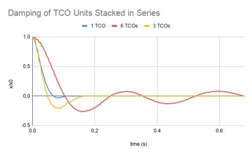 Figure 13. As more TCO units are stacked in series, the system becomes less damped
 -
 Figure 14. Percent energy loss of the tennis ball after one bounce on the TCO system
 -
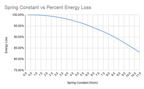 Figure 15. TCO systems with a spring constant between 0 and 1.0 will absorb almost 100% of the tennis ball's energy


Conclusion
editTCO stacks may be able to be used as the legs for a robot designed to survive a fall from a great height. These TCO stacks are able to absorb almost 100% of the energy from a falling tennis ball, especially when there are multiple stacks in parallel. TCO units are able to be modeled as mass-spring-dampers and will behave accordingly when combined into a system of units. Using a mass-spring-damper model, the behavior of any TCO system is able to be predicted when the mechanical properties of an individual TCO unit are known. A specific arrangement of TCO units could be incorporated into a robotic system in order for a given amount of energy to be absorbed when the robot makes impact with the ground or any other obstacle. Using paper to create these units is a low cost, low weight alternative to using traditional spring-dampers that could accomplish the same thing.
Additional information
editAcknowledgements
editThe professors and staff at the Rutgers University Department of Mechanical and Aerospace Engineering and the Rutgers Lab for Machines, Manufacturing, and Mechatronics.
Competing interests
editThe authors have no competing interests.
References
edit- ↑ Srinivas, Bairy (2016). "Reduction in the Impact Force on a Vehicle Using Spring Damper System". International Journal of Engineering Research and General Science. 4 (1): 309-314. ISSN 2091-2730.
- ↑ Bernzen, Werner (1999-01-01). "Active Vibration Control of Flexible Robots Using Virtual Spring-damper Systems". Journal of Intelligent and Robotic Systems 24 (1): 69–88. doi:10.1023/A:1008035116904. ISSN 1573-0409. https://doi.org/10.1023/A:1008035116904.
- ↑ Baruh, Haim & Elsayed, Elsayed. (2018). "Experimental design of a folded-structure energy-absorption system". International Journal of Materials and Product Technology. 56 (4): 341-362. doi: 10.1504/IJMPT.2018.10010777. ISSN 1741-5209.
- ↑ 4.0 4.1 Yasuda, Hiromi; Miyazawa, Yasuhiro; Charalampidis, Efstathios G.; Chong, Christopher; Kevrekidis, Panayotis G.; Yang, Jinkyu (2019-05-01). "Origami-based impact mitigation via rarefaction solitary wave creation". Science Advances 5 (5): eaau2835. doi:10.1126/sciadv.aau2835. ISSN 2375-2548. https://advances.sciencemag.org/content/5/5/eaau2835.
- ↑ Li, J.; Godaba, H.; Zhang, Z. Q.; Foo, C. C.; Zhu, J. (2018-10-01). "A soft active origami robot". Extreme Mechanics Letters 24: 30–37. doi:10.1016/j.eml.2018.08.004. ISSN 2352-4316. http://www.sciencedirect.com/science/article/pii/S235243161830138X.
- ↑ 6.0 6.1 Zakrzhevskii, A. E. (2016-04-11). "Method of Deployment of a Space Tethered System Aligned to the Local Vertical". The Journal of the Astronautical Sciences 63 (3): 221–236. doi:10.1007/s40295-016-0087-z. ISSN 0021-9142. http://dx.doi.org/10.1007/s40295-016-0087-z.
- ↑ Li, Shuguang; Vogt, Daniel M.; Rus, Daniela; Wood, Robert J. (2017-11-27). "Fluid-driven origami-inspired artificial muscles". Proceedings of the National Academy of Sciences 114 (50): 13132–13137. doi:10.1073/pnas.1713450114. ISSN 0027-8424. http://dx.doi.org/10.1073/pnas.1713450114.
- ↑ 8.0 8.1 Schenk, Mark; Viquerat, Andrew D.; Seffen, Keith A.; Guest, Simon D. (2014-05). "Review of Inflatable Booms for Deployable Space Structures: Packing and Rigidization". Journal of Spacecraft and Rockets 51 (3): 762–778. doi:10.2514/1.A32598. ISSN 0022-4650. https://arc.aiaa.org/doi/10.2514/1.A32598.
- ↑ Zou, Xiyue; Liang, Tongfen; Yang, Michael; LoPresti, Cora; Shukla, Smit; Akin, Meriem; Weil, Brian T.; Hoque, Salman; Gruber, Emily; Mazzeo, Aaron D.. "Paper-based Robotics with Stackable Pneumatic Actuators". In Revision.
- ↑ "Mass-spring-damper model". Wikipedia. 2020-02-16. https://en.wikipedia.org/w/index.php?title=Mass-spring-damper_model&oldid=941090018.
- ↑ 11.0 11.1 Zhai, Zirui; Wang, Yong; Jiang, Hanqing (2018-02-27). "Origami-inspired, on-demand deployable and collapsible mechanical metamaterials with tunable stiffness". Proceedings of the National Academy of Sciences 115 (9): 2032–2037. doi:10.1073/pnas.1720171115. ISSN 0027-8424. http://www.pnas.org/lookup/doi/10.1073/pnas.1720171115.
- ↑ "Tracker Video Analysis and Modeling Tool for Physics Education". physlets.org. Retrieved 2020-12-02.