Arduino/ESC Programming
ESC stands for "Electronic Speed Control". These are found in remote control aircraft that need to spin their motors at different speeds.
Target Audience
editSomeone who has loaded the arduino IDE, blinked pin 13 and has a speed controller plus a motor and power supply.
Starting Point
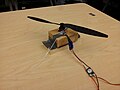
editMotor, ESC, arduino and Potentiometer mounted on a board.
Replication Goal
editWire up everything, download knob arduino example program, and turn Potentiometer knob to start, stop and change motor speed.
Procedure Mount Everything on a Board ... Be Safe !!!
edit-
 Do not attach propeller and try to fly immediately
 -
 the propeller can cut your finger off
 -
 It can cut wires and destroy equipment
 -
 The can above the wires spins, there is a piece on the bottom that spins, a brushless outrunner motor can start up at any time
 -
 Everything mounted on a board, propeller off, power disconnected, the most safe


- Step: The DC brushless outrunner motor spins practially everything that one could touch, it comes with mounting brackets that need to be screwed into some wood. Sometimes a hole needs to be dug into the wood.
- Step: The wires will break inside the ESC and ruin it if the ESC is left dangling. Mount the ESC on some wood.
- Step: The arduino has holes in it to mount it on wood
- Step: The Potentiometer will have be mounted so that one hand can be used to control the motor speed
Procedure Connect Power wires
edit-
 separate red and black wires going to the right power the ESC and motor
 -
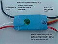 another ESC showing separate red and black wires going to the right that power the ESC and motor
 -
 Power to both ESC's is not connected to a battery in this picture
 -
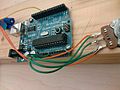 power is flowing from the ESC through the orange wires to the pot, and from the pot's outside green wires to the arduino
 -
 this shows arduino ground connected to the ESC for reference purposes, Arduino is not getting power from the ESC
 -
 shows power coming in the greenand orange lines from right side of picture


- Step: Find thick red and black wires that supply power to the ESC
- Step: Leave the ESC disconnected from power to prevent motor accidentally starting up
- Step: Find bundle of two or three thick wires that power the motor
- Step: Leave motor disconnected unless it is in use, motors have randomly started before and scared everyone
- Step: Find the bundle of three tiny wires glued together attached to the ESC: (brown is ground, red is power out, orange is data in)
- Step: Connect the three tiny wires to the arduino: orange goes to a pwm digital pin, brown to ground and red to Vin.
The ESC handles the most dangerous current that flows through it to the motor. Hook the motor up first and then power to the ESC.
Procedure Connect the Potentiometer
edit-
power is flowing from the ESC through the orange wires to the pot, and from the pot's outside green wires to the arduino
-
 the middle wire goes to analog 0, the brown wire from the ESC bounces off the pot and goes to ground, the red wire from the ESC bounces off the pot and goes to Vin

- Step: Find a pot, solder a pair of solid wires to the outside terminals of the pot, and one wire to the center
- Step: run the center wire to arduino analog 0, and the pot edges to GND and Vin
- Step: connect the other wires to the ESC connector so that red goes to Vin and brown goes to GND
Wire color varies between ESCs, here are some common colors and functions (note that because both power and control may have the same voltage on some ESCs they may be interchangeable):
- Power/Positive Voltage -> Red
- Ground -> Black, Brown
- Control -> White, Orange
Procedure Power on Check
editConnect power to the ESC and:
- listen to a chirp noise from the ESC, this means it has powered on and found the motor
- watch the motor, it may twitch when initially powering on, this is the ESC using back EMF to figure out which way the motor is going to rotate
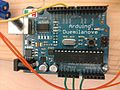
- look at the LED's on the arduino to make sure it is alive
Various ESC's and motors are going to behave slightly different. Some may not chirp or twitch their motor.
Try to find the Manual. The trouble is most manuals document how to use a remote control and remote receiver connected to the ESC rather than just how the ESC itself works. After looking through several ESC manuals it appears that the power on step sequence (maximum) could be:
- power on
- spin
- determine number of cells in the lipo
- choose the braking system
Procedure to start motor and control speed
editThese steps require fiddling. So here is some background:
- ESCs require pulses to be sent to them 50 times a second or 50 Hz.
- Pulses can have different widths: from about 0.5 ms to 2.5 ms (millisecond).
- A sequence of various pulse widths, timed pauses and then new pulse widths causes the motor to move and change speed.
- The exact sequence is usually not documented
The reason for the potentiometer is to vary the pulse width and pauses. Just start wiggling the potentiometer back and forth. The ESC may chirp two times or three times, or try to communicate with you in morse code. Who knows.
- Step Download the knob program into the arduino
- Wiggle potentiometer.