Hamming
Problem/Finish Description
editIntroduction to Hamming Code for Error Detection and Correction
In the world of digital information, accuracy and reliability are paramount. Whether it's transmitting data across wireless networks or storing critical information on hard drives, errors can creep in and compromise the integrity of the data. This is where error detection and correction techniques play a crucial role. One such pioneering method is the Hamming Code, a mathematical construct that has revolutionized error detection and correction in various domains, including communication systems and data storage devices.
The Hamming Code, named after its inventor Richard Hamming, presents an elegant solution to the age-old problem of identifying and rectifying errors that can occur during data transfer. This article delves into the intricacies of the Hamming Code, exploring its fundamental principles, applications in error detection and correction, and a practical demonstration of its implementation on both hard drives and communication systems, whether wired or wireless.
Conceive
editIntroduce Electrical/Computer Engineering by simulating circuit board on bottom of hard drive:
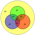
- Hamming(7,4) Code
- Digital Class (typically freshman or sophomore year)
- Discrete Math Class (typically freshman or sophomore year)
- FPGA VHDL Lab Class (becoming a sophomore class ... mostly senior class)
Design
edit-
 Digital Design Classes use graphical techniques to design circuits including hamming(7,4)
 -
 digital logic diagram for hamming(7,4) receive circuit that is taught in digital logic class
 -
 boolean code for hamming(7,4) code receive circuit that is taught in a discrete math class
 -
 Hamming(8,4) another hamming code that could be implemented with the hardware below
 -
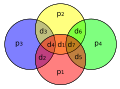 Hamming(11,7) corrects/detects more errors
.svg)


.svg)
.svg)
- Video on how to use the graphical technique
- Hamming recevieve circuit animation
- Link to Logisim (open source .. free software)
- Link to the logisim circuit used for the screen shot and the video
Implement
editUsed 8 slide switches and 7 LED's to implement this demonstration of hard disk drive corrective circuitry.
-
 Flow chart describing physical implementation of hamming(7,4) with 8 switches and 7 LEDs
 -
 User Constraints File (UCF file) used with Xilinx IDE showing how LogicWing is physically connected to the pins of the FPGA on the Papilio
 -
 VHSIC Hardware Description Language (VHDL) file colored with NotePad++ VHDL shell showing the hardware description language of this circuit


|
- OpenSource hardware platform chosen papilio
- Switches and LEDs provided by the LogicStart MegaWing
- Drew the flow chart with Lucid Chart ... which is free with an email ending in *.edu .. name is Hamming Circuit Outline
- The UCF file was created from various sources
- It was implemented in one hardware entity .. one VHDL file
- Scanned engineering notebook pages written during this process
- The bit file (the code actually sent down USB cable to the Papilio) was created Xilinx ISE Design Suite
- The bit file is sent down the USB cable to the Papilio using the papilio loader
- The colored template or shell for displaying the VHDL code was found in OpenSource editor Notepad + +
- The graphics above were edited with the open source photo editor gimp.
Operate
editThis is the intended sequence:
- Practice the graphical technique on paper
- Operate the physical circuit
- Study how the receive/corrective circuit operates in the design above
- Figure out all the software pieces to generate the bit file
- Take a digital design class and a lab and become an electrical/computer engineer
-
 Print out to introduce students to the graphical technique for understanding error correction
 -


Demo
edit- Printout this page on paper to hand to everyone in the audience
- Presentation
- Video
Next Steps
editThe algorithm for correcting many bits is well known. Demonstrating this at a larger scale is going to require some imagination.
- How do we corrupt bits on demand, accurately, in a way that can be checked?
- What hardware is going to display this?