Commercial diving/Basic underwater rigging
Relevance: Scuba diving (partial: not winches and tuggers, light lifting bags), Surface supplied diving (full), Surface oriented wet bell diving.
Required outcomes:
- Describe the safe, effective and appropriate use of winches and tuggers
- Describe the safe, effective and appropriate use of wire ropes, slings, cargo nets and spreaders
- Describe the safe, effective and appropriate use of airbags for lifting loads
- Describe the safe use of purchases, tackle, turning blocks, shackles, hooks, cordage, knots, lashings and splices
Lifting bags (Buoyant lifting)
editA lifting bag is an item of diving equipment consisting of a robust and air-tight bag with straps, which is used to lift heavy objects underwater by means of the bag's buoyancy. The heavy object can either be moved horizontally underwater by the diver or sent unaccompanied to the surface.
Lift bag appropriate capacity should match the task at hand. If the lift bag is grossly oversized a runaway or otherwise out of control ascent may result. Commercially available lifting bags may incorporate dump valves to allow the operator to control the buoyancy during ascent, but this is a hazardous operation with high risk of entanglement in an uncontrolled lift or sinking. If a single bag is insufficient, multiple bags may be used, and should be distributed to suit the load.
Physics of buoyant lifting
editThe volume of the bag determines its lifting capacity: each litre of air inside the bag will lift an apparent weight of 1 kilogram force. For example, a 100 litre bag can lift a 100kgf underwater object.
A partially filled bag will accelerate as it ascends because the air in the bag expands as the pressure reduces on the ascent, following Boyle's law, increasing the bag's buoyancy, whereas a full bag will overflow or blow off excess volume and maintain the same volume and buoyancy providing is does not descend. A bag which leaks sufficiently to start sinking will lose volume to compression and become less buoyant in a positive feedback loop until stopped by the bottom.
In theory it is possible to calculate the weight of the object to be lifted and therefore the amount of buoyancy needed. In practice this is not easy, and is complicated by the object being partly buried and stuck in the sand or mud.
Density of water
edit- Fresh water 1000 kg/m3
- Sea water about 1030 kg/m3
Apparent weight of submerged object
editThe apparent weight of an submerged object is the difference between the weight in air and the buoyancy. This is often called negative buoyancy by divers, but the term is not accurate. This is the load that must be lifted to move the object upwards in the water.
Calculation is simple if the volume of displacement and the average density are known, but this is not always the case. The value is often approximated when the mass is known by estimating a reasonable value for density or specific gravity, and using this to get an approximate value for the apparent weight. It is common in these calculations to use kilogram-force (kgf or kgf) for the unit of weight as the lifting volume required is then easily converted to litres, or tonne-force (tf or tf) and volume in cubic metres.
| We start with the equation: | ||||||
| Apparent weight | = weight of the load in air − weight of the water displaced | or | Wa | = W-Ww | ||
| = weight in air − displaced volume × density of water × gravitational acceleration | = W-V×ρw×g | |||||
| However, | ||||||
| Displaced volume | = weight in air ÷ (density of load × gravitational acceleration) | V | = W/(ρl×g) | |||
| Therefore, by substituting this into the original equation, we get | ||||||
| Apparent weight | = weight in air − (weight in air ÷ (density of load × gravitational acceleration)) × (density of water × gravitational acceleration) | Wa | = W-(W÷(ρl×g))×(ρw×g) | |||
| = weight in air × (1 - (1 ÷ (density of load × gravitational acceleration) × (density of water × gravitational acceleration)) | = W×(1-(1/(ρl×g))×(ρw×g) | |||||
| = weight in air × (1 − (1 × density of water ÷ density of load)) | = W×(1-(1×(ρw×g)/(ρl×g)) | |||||
| = weight in air × (density of load - 1 × density of water) ÷ density of load | = W×(ρl−1×ρw)/ρl | |||||
| to finally get: | ||||||
| Apparent weight | = weight in air × (density of load - density of water) ÷ density of load | Wa | = W×(ρl-ρw)/ρl | |||
Example:
- An object known to weigh 2500 kgf in air, is made of steel with a density of 7.8 kg/l.
- Apparent weight in fresh water with density 1 kg/l = 2500 x (7.8-1)/7.8 kgf = 2179 kgf
Buoyancy of lift bags
editBuoyancy of lift bag = Volume of water displaced x density of water displaced
Example: Buoyancy required for a lift bag:
- An object of mass 1.2 tonnes, specific gravity 2.3 is to be lifted using an air bag in sea water with density 1030 kg/m3
- Apparent weight of the object:
- Mass = 1200kg, Density = 2300kg/m3
- Volume = 1200/2300 = 0.522 m3
- Buoyancy = 0.522 x 1030 = 538 kg
- Apparent weight = 1200 – 538 = 662 kg
- Volume required to lift = 662/1.030 = 643 litres
Example: Buoyancy assisted lift:
- An object with an apparent weight of 6124 kgf is to be lifted from 35 m depth
- You have a 5 tonne lift bag, what additional force is required to lift the load?
- Lift provided by the bag is approximately 5000kgf (depending on water density, but the difference is less than the margin of error)
- Residual load is approximately 6124-5000 = 1124 kgf
- Note that inertial loads could be much more than this value.
Types and construction
edit- Parachute (open ended) bags should be fitted with a suitable attachment point at the top to which a tripping line can be attached.
- Parachute bags should have a dump valve which can be operated by a line, usually running down inside the bag which can be easily reached by the diver and operated from a safe location. (weighted dump valves}
- The tripping line and dump line should be easily distinguished in poor visibility
- Closed lift bags must have overpressure relief valves.
- If the bag is designed to be used in the horizontal position it must be rigged so that it can not rotate to a vertical position
Open lift bags (parachute lift bags)
edit
Parachute lift bags are open at the bottom. When full any extra or expanding air will spill out. The shape of an open lifting bag should distribute the volume in a vertical rather than a horizontal direction so that the open end of the bag always remains underwater. If the open end reaches the surface, air will escape from the bag and it may sink.
The simplest version are two-sided bags, either joined round the edges or folded and joined along two sides. Webbing straps may be stitched to doubler patches which are then glued or welded to the bag on light duty bags, but on large and heavy duty bags there are usually strips of bag material bonded to the bags which form flat retaining tubes for the webbing which is threaded through the tubes and may be withdrawn for maintenance and inspection. heavy duty open bags are generally conical with a domed top or a reversed truncated cone top, and may have several straps from the lifting point at the bottom, through the guide tubes on the sides, to a crown ring of webbing or steel at the top, to spread the load evenly over the fabric of the bag.
Parachute lift bags cannot be overfilled and are suitable for lifts where there is a large pressure change, and where it may be necessary to capsize (invert) the bag to stop a runaway lift.
Some lift bags can be converted from open to closed by screwing a cover onto the bottom opening.
-
 Open (parachute) lift bag.
 -
 Small recreational grade lift bag.
 -
 Medium duty 50 kg lift bag
 -
 Small Lift bag rolled up for transport


Closed lift bags (camels)
edit

Closed lift bags have an overpressure valve to prevent internal pressure from exceeding ambient pressure by more than a set amount (around 10kPa, or 1msw) Closed lift bags are intended for use at or near the surface, as they retain the air even in rough seas. They are available in several configurations, including horizontal cylinder, vertical cylinder, teardrop and pillow.
Rapid deployment
editRapid deployment lift bags have a scuba cylinder mounted on the outside which contains sufficient air to inflate the bag at a specified depth. The bag can be attached to the load and when ready, the valve is opened and the diver swims clear. If the regulator pressure is set to a lower pressure than the over-pressure relief valve, a closed bag will automatically stop filling before the relief valve opens, but will be topped up if it leaks after reaching the surface. The regulator pressure must take into account the hydrostatic pressure difference between the top and bottom of the bag so that the bag will be completely filled.
Specifications
editUnderwater lifting bags are lifting equipment and as such may be required to comply with safety standards. Lifting bags should be specified regarding safe working load, maintenance and testing. Accessories such as strops, rings, shackles must be rated for more than the rated load of the bag as snatch loads can exceed the buoyancy of the bag
Dump valves
editDump valves are used to release air from the bag when in the water. They can be operated manually at the valve by a diver or may be remotely operated by a pull-cord, which may be operated by a diver or attached to a weight which will automatically open the valve if the weight is lifted off the bottom. Some dump valves can be operated in both these ways. One system operates by pressing on the top or pulling a line attached to the bottom to actuate the spring-loaded valve. The dump valve may be a screw-in quick change system, and the spring tension may be adjustable.
Use
editThe force required to lift a submerged object from the bottom can be split into two main components:
- Apparent weight, which is the weight of the object less the buoyancy of its displacement.
- Breakout forces due to embedment in the bottom, which can be negligible, or in some cases the major part of the load.
Breakout
editOnce the object has broken free of the bottom, only the apparent weight remains, and a controlled lift requires a way of managing the sudden decrease of resistance to the lifting force. There are three basic ways this can be done:
- Use of mechanical or hydraulic excavation to loosen the sediments holding the load.
- Use of a "Dead Man Anchor" - a large heavy weight - and restraining cable to prevent the bag from moving away too far, so that the buoyancy can be corrected to more closely match the load.
- Use of shallow bags with long cables to the load to provide breakout, which will only lift a short distance before surfacing, after which the load can be lifted further by staged lifts, direct lift by close-coupled bags, or buoyancy assisted lift, where part of the load is taken by the lift bags, and the rest by lifting gear at the surface, which allows fine control of ascent rate and eliminates the hazard of a runaway ascent.
Stability of the load
editOnce a load is lifted off the substrate, it will rotate until the centre of gravity is in the position of lowest potential energy. If it is suspended from a single point, the apparent centre of gravity (corrected for inherent buoyancy) will be directly below the lift point. If it is undesirable for the load to rotate by a large angle as it leaves the bottom, the lifting point or points must be chosen to allow for this effect, a multi-part sling or spreader bar may be needed, and it may be necessary to secure slings so they do not slip.
Dynamic lifts
editWhen the empty lift bag is attached to the load and the lift is made by controlling the volume of inflation air it is referred to as a dynamic lift.
Direct lift
editThe bag or set of bags is used to lift the load directly to the surface. This is simple, but there is a risk if the lift bag is too large and cannot be vented fast enough the lift may get out of control and ascend so fast that the bag breaks the surface, capsizes and collapses, losing so much air that it then cannot support the weight of the load, and will then sink back to the bottom. If there is a marker buoy attached it will at least not be lost. A lift bag which is only slightly larger than needed to support the load will ascend more slowly, and is less likely to capsize at the surface, as excess air will be spilled continuously during the ascent.
Staged lift
editLift bags are used to bring the load up in stages: a long chain or sling is used to connect the load to a lift bag just below the surface, which is filled to break out the load and lift it until the bag reaches the surface, then a second bag is used to bring the load up further. This procedure continues until the load has been raised sufficiently. Advantages of this method are a more controlled lift, the facility to use a larger capacity for initial breakout without risk of a runaway. Disadvantages include the requirement for divers to work on or near the lifting gear when under load.
- It may be safer of more convenient to lift a load in stages, where the lift bag is tethered on a line which allows the bag to be filled and take the load near the surface. This allows an embedded load to be broken free by using a large excess of buoyancy without allowing a rapid uncontrolled ascent. Less air is needed for the breakout as it is used near the surface where the pressure is lower.
- Attach slings to the load in the normal way and use a cable of sufficient length to hold the bag under water at a depth where stretch and breakout movement will just lift the load off the bottom when the bag surfaces.
- After breakout additional bags may be used to bring the load to the desired depth, either at once or by a similar staged process.
Buoyancy assisted lift
editThe lift is controlled by a line from the surface vessel, and the load is reduced by a lift bag with a volume too small to support the weight of the load when full. This allows a faster lift by the winch. The lifting gear must be capable of supporting the load if the bag fails, or must be arranged to fail safely.
A buoyancy assisted lift is a common procedure for recreational divers to assist the recovery of the shotline or anchor, which would otherwise be pulled up manually. A small lift bag attached to the shot is partially filled by the last diver to leave the bottom, and after surfacing the crew pull up the line and the air in the bag expands as it ascends, providing more assistance to the crew. In this application a runaway lift is not usually a problem, and the bag size is not critical.
Static lifts
editLift bags also can be used for static lifts, where the bag is anchored in place by rigging, and used as a lifting point with very high buoyancy compared to the load, which is then lifted in a controlled manner using a purchase or chain block or other suitable lifting device.
For static lifting the lift bags can be located at depth and anchored to the bottom or can float at the surface. Floating at the surface subjects the bag to fluctuating wave loads, and the movement and loads are transferred to the load, so it is not always useful.
Static lifting with bottom anchored bags gives the divers precise control over the lift, and requires suitable anchoring systems for the lift bag, which usually entails heavy lift equipment at the surface to put the anchors in place. This procedure is useful when the lifting capacity is available, but precise control of a surface equipment lift is not practicable. For example, sea conditions may cause the lifting vessel to move too much for the control needed for the work. Replacing a heavy valve on a seabed manifold may be done this way, particularly if the bag can be anchored to the manifold.
Rigging lift bags
edit

Lift bags can not be over inflated, and can not normally exert a static buoyant force greater than their safe working load, however the rigging can be subjected to snatch loads, which can be caused by a variety of factors.
- When the bag is used in shallow water and surge or wave action causes rapid changes in dynamic loading, by pulling the bag from side to side
- When the bag has lifted the load to the surface and the bag is subjected to vertical wave action
- When the lift bag is incorrectly rigged
- When the lift bag is snagged, then breaks free to be snubbed when the slack is taken up.
- When the load is partly supported by a lifting cable and there is a sudden variation on the tension in the cable due to vessel movement or cable slip.
When lifting with more than one bag, allowance should be made for reduced filling capacity if bags are attached in such a way that they press against each other.
Incorrect rigging can cause load concentration on attachment points which may exceed the Safe Working Load (SWL).
A inverter or capsizing line can be attached to the top of the bag. This line should be long enough and strong enough to attach to an independent anchor point so that if the lift bag or rigging fails the bag will be inverted and the air will escape, preventing a runaway lift. This procedure is generally used for short distance transport near the bottom, as when aligning large components for assembly. With this method the load will generally hold the bag in the upright position, so the tripping line may be subjected to considerable load and the bag may not invert. An inverter line can also be attached to the load, so it will capsize the bag if it breaks free of the load, but this will not stop a runaway lift, and a holdback line is used for this purpose.
A holdback line is used to prevent the lift bag and load from floating away when used for short distance lifts at the bottom. The holdback is attached to the lifting ring of the bag, or to the load, and should be attached by a strong cable to an anchor point it cannot lift. The SWL of the holdback should be at least equal to the lifting capacity of the bag. A holdback and inverter are often used together.
A spreader bar may be used to distribute the lifting load more evenly between bags or along the load.
When filling bags, if each bag is completely filled before starting to fill the next bag, it is less likely that a runaway will be initiated, as only one of the bags can increase lift as it ascends. This will be the last bag, and the divers will be monitoring it most carefully while they are filling it, so will be more likely to react in time to regain control of the lift.
A weighted dump line will automatically start open the valve to start dumping excess air if the weight is lifted off the bottom. This will stop the lift from ascending any further if the dump valve releases air fast enough. When the weight is lowered back to the bottom by the sinking load, the valve will close again, and should hold the load steady. The stability of this system depends on the pre-load of the valve spring and the size of the valve opening.
Filling lift bags
editThe amount of air required for a lift bag depends on the apparent weight of the load and the depth of the bag. Approximately 1 m3 of air at ambient pressure is required per tonne of lift. Free air volume follows Boyle's law, and is proportional to absolute ambient pressure in bar or ata.
For example:
- A 5 tonne lift with the bags to be filled at 20m, requires 5m3 of air at 3 bar, which is 15m3 at surface pressure.
Filling air is usually supplied from the surface from a low pressure compressor, but for small lifts a scuba diver may carry a cylinder of air for the purpose, or use the pneumo line. It is considered bad practice to fill a lift bag from the diver's breathing gas cylinder, particularly if the diver has decompression obligations or only one cylinder as the risk of using up too much air and leaving the diver without sufficient air for a safe ascent is unacceceptable.
Bags can be inflated from a safer distance by use of an air-lance (a rigid pipe which can be inserted into the opening of the bag), or remotely from the surface if the filling line is direct coupled to the lifting bag. This allows filling when the diver is out of the water.
Hazards of use
edit- Snagging of the diver or diver's umbilical or lifeline in the lifting equipment, resulting in an uncontrolled rapid ascent.
- Using too much air from scuba diver's breathing gas supply, resulting in an out of air incident.
- Using too much volume in the lift bags, resulting in a positive feedback expansion on ascent and a runaway lift.
- Leaks in lift bags, causing loss of buoyancy and sinking of the load after lifting. The load may then sink increasingly rapidly as the air in the bags compresses, and may be a hazard to divers below or working on the load at the surface, or the load may be lost.
- Unbalanced attachment of lifting gear may cause the load to be unstable once lifted free of the bottom. subsequent capsize or shifting of the load may break it free of the rigging, or damage the load or the lift bag. Similarly, poorly chosen or inadequate lifting points may result in overstressing the cargo and causing damage.
-
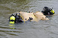
 Divers releasing air from a lift bag underwater.
 -
 Divers on the surface with lift bags.
 -
 Underwater archeologists position a lift bag to readjust shoring during the excavation of the U.S. sloop-of-war Scorpion.
 -
 Training Navy divers in to operate lift bags.
 -
 Navy training exercise using lift bags.


Purchases, tackle, turning blocks, shackles, hooks, cordage, knots, lashings and splices
editMechanical advantage of a tackle system.
edit- In a multi-part purchase the load is evenly distributed among the parts of the cable.
- If the parts are parallel the advantage of the tackle can be calculated by dividing the total load by the number of parts leading to the moving block.
Useful accessories for small scale rigging
edit- Prusik Knots, Rope Grabs and Ascenders (Jumars)
- A Prusik is a friction hitch used to grab a rope (sometimes referred to as a rope-grab).
- The knot is made using a "Prusik Loop" which is constructed by joining the two ends of a length of rope using a Double or a Triple Fisherman's bend. The prusik loop should be smaller diameter rope than the rope it is to be used on. It is not suitable for use on slippery ropes such as polypropylene ski-rope
- Prusiks will work around two ropes, even two ropes of different diameters. Prusiks provide a high-strength and relatively fail-safe (i.e., they will slip before damaging the rope or breaking) attachment, and are used in some rope-rescue techniques. Prusiks are good to use in hauling systems where multiple rope-grabs may be needed, and where mechanical rope-grabs are not available.
- A Rope Grab is a mechanical device which will slide along a rope in one direction and lock in the other direction. It works in a similar way to an Ascender.
- An Ascender or Jumar is a mechanical device for ascending on a rope. It can also be used to attach an object to a rope without the use of a knot.
- Ascenders offer similar functionality to Prusik knots but are stronger, faster, safer and easier to use. An ascender uses a cam which allows the device to slide freely in one direction, and provide a firm grip on the rope when pulled on in the opposite direction. To prevent an ascender from accidentally coming off the rope, a locking mechanism or trigger is deployed.
- Snap shackles
- A snap shackle is a quick action fastener which can be operated single handed. It uses a spring activated locking mechanism to close a hinged shackle, and some models can be unfastened under load. This is a potential safety hazard, but can also be extremely useful at times. The snap shackle is not as secure as other forms of shackle, but can come in handy for temporary uses or in situations which must be moved or replaced often or quickly. Note: When this type of shackle is used to release a significant load, it may be hard to release.
- Snatch blocks
- A snatch block is a pulley block that can be opened on the side to receive or remove the bight of a rope.
Winches and tuggers
editTirfors
editChain hoists
editLever ratchet hoists
editRopes, slings,nets and spreaders
editLifting with a crane or derrick
edit- The effect of a weight hanging from a cable is that the effective centre of gravity of the lifted object is applied at the top of the lifting cable where it passes over the first fixed sheave of the crane or derrick. This may have significant effects on the stability of a vessel.
Wire ropes and slings
edit- Most wire ropes for slings are made from 6 strands laid around a fibre core. The core carries lubricant and allows the rope to bend with less stress.
- The strands are made of continuous wires running the full length of the rope. The number of wires in a strand depends on the application. A large number of small strands makes a flexible rope. A smaller number of larger wires is more resistant to wear and corrosion, but is less flexible.
- Galvanised wire and in some cases stainless steel, is used to resist corrosion. Stainless steel can be more susceptible to fatigue and stress-corrosion cracking.
- The size of a wire rope is normally given as its largest diameter, and it may also be classified according to the number of wires and strands.
- Example: Wire rope classification:
- 6x19 (12-6-1) rope consists of 6 strands, each of 19 wires which are laid with 12 wires around 6 wires around a central wire.
Safety factor
edit- For general lifting a wire rope should have a safety factor of 5. In other words the rope should not be used for tensions which are more one fifth of the breaking strain.
- No equipment should be used for loads greater than the safe working load (SWL)
- For lifting where personnel are part of the load the factor of safety should be at least 8.
Minimum sheave diameter
editTypes of sling
edit- A single part sling is made from a single length of rope with an eye splice and thimble at each end.
- A double part sling is made from a loop with thimbles seized into each end of the stretched loop.
Load in slings
edit- The tension in a sling depends on the angle of the cables and number of the cables (legs), and where they are attached to the load relative to the centre of gravity
- There is no guarantee that more than two legs will share the load. Even load sharing requires correct distribution of connection points and length of sling legs
- Legs attached near the centre of gravity may carry proportionately greater loads
- Load in a leg is inversely proportional to the cosine of the angle to the vertical.
- At 45° the load is 1.4 times the vertical load
- At 60° the load is double the vertical load.
- As the angle gets larger the load increases rapidly.
- The load in shackles and hooks attaching the leg to the load is the same as the load in the leg.
- All components of the lifting equipment must be within their Safe Working Load
Spreader beams
editA more even load distribution may be achieved by using spreader beams.
Stability of load
edit- Before rigging for a lift consider the consequences of the load changing orientation as it leaves the bottom.
- If the lifting gear is not attached directly over the centre of gravity of the load it will rotate during the start of the lift until the centre of gravity is under the lifting gear.
Lifting the load out of the water
editThe tension in the lifting gear will suddenly increase as the load leaves the water as the buoyancy is lost, and may also be increased by trapped water.
Safety rules for lifting
edit- Establish an effective system of communication
- Ensure that you use a well understood and uniform code of signals
- Ensure that there is only one designated signaller. A stop signal can be given by anyone in an emergency.
- Check that the area is clear before lowering a load
- The signaller must never signal to lift until cleared by the person slinging the load
- No person may ride on a load.
- Awkward loads should be given a trial lift to check stability and security
- Use the correct type of slings for the load
- Only attach slings to designated lifting points or as instructed by a competent person
- Protect slings from sharp edges and abrasion by using padding
- Use four legged slings on trays and pallets. Fix a net if necessary to prevent items from falling off.
- Use spreaders where appropriate
- Always raise and lower loads smoothly, and lower immediately if the load shows signs of slipping.
- Do not lift over personnel or allow personnel to walk under loads.
- Do not leave winches or craned unattended with loads slung.