Cisco Networking/CCENT/Collection
Cisco CCENT
editLearning Guide
editThis learning guide supports the Wikiversity course Cisco CCENT, available at http://en.wikiversity.org/wiki/Cisco_Networking/CCENT.
Overview
editCisco Networking/CCENT/Collection/Sidebar
Cisco Certified Entry Networking Technician (CCENT) includes ability to install, operate and troubleshoot a small enterprise branch network, including basic network security.[1]
This course comprises 15 lessons covering Cisco networking. Each lesson includes a combination of Wikipedia and Cisco readings, YouTube videos, and hands-on learning activities. The course also assists learners in preparing for Cisco CCENT (Interconnecting Cisco Networking Devices Part 1) certification.
Preparation
editThis is a fourth-semester, college-level course. Learners should already be familiar with introductory computer networking concepts and Internet protocols.
Lessons
editSee Also
editBibliography
edit- Cisco: 100-101 ICND1 Exam Topics
- Cisco: ICND1 Study Material
- Cannon, Kelly and Caudle, Kelly (2009). CCNA Guide to Cisco Networking Fundamentals. Cengage. ISBN 9781418837051
- Cisco: Internetworking Technology Handbook
- Lammle, T. (2013). CCENT Study Guide: Exam 100-101 (ICND1). Wiley. ISBN 9781118749685
- Odom, W. (2013). CCENT/CCNA ICND1 100-101 Official Cert Guide. Cisco. ISBN 9781587143854
References
editLesson 1 - Networking Models
editThis lesson covers the TCP/IP and OSI networking models and encapsulation concepts.
Objectives and Skills
editObjectives and skills for the TCP/IP and OSI networking models portion of Cisco CCENT certification include:[1]
- Describe the purpose and basic operation of the protocols in the OSI and TCP/IP models
- Recognize the purpose and functions of various network devices such as routers, switches, bridges and hubs
- Identify common applications and their impact on the network
- Predict the data flow between two hosts across a network
Readings
editMultimedia
edit- YouTube: The OSI Model - CompTIA Network+ N10-005 - 1.1
- YouTube: The OSI Model in the Real World - CompTIA Network+ N10-005: 1.2
- YouTube: The TCP/IP Model - CompTIA Network+ N10-005: 1.1
- YouTube: Networking Protocols - CompTIA Network+ N10-005: 1.6
- YouTube: Network Layers - OSI, TCP/IP Models - Part 1
- YouTube: Network Layers - OSI, TCP/IP Models - Part 2
- YouTube: Network Layers - OSI, TCP/IP Models - Part 3
Activities
edit- Review OSI Components. Describe the purpose and basic operation of the layers in the OSI and TCP/IP models.
- Draw your own personal reference chart comparing the Internet protocol suite four-layer model to the OSI seven-layer model.
- Use Wireshark to capture network traffic on your school, work, or home network. Identify the protocols in use on the network at each layer of the OSI and TCP/IP models.
- Use Wireshark to capture network traffic on your school, work, or home network. Identify the protocol data unit headers and layer interaction as data is encapsulated from segment to packet to frame for transmission as bits.
Lesson Summary
edit- The Open Systems Interconnection model (OSI Model) is a conceptual model that characterizes and standardizes the communication functions of a telecommunication or computing system without regard for the underlying internal structure and technology.[2]
- The OSI model is a seven-layer model containing Physical, Data Link, Network, Transport, Session, Presentation, and Application layers.[3]
- The OSI model layers are numbered from the bottom up:[4]
- 7 - Application
- 6 - Presentation
- 5 - Session
- 4 - Transport
- 3 - Network
- 2 - Data Link
- 1 - Physical
- The OSI model is maintained by the International Organization for Standardization (ISO).[5]
- The OSI Physical layer transmits and receives raw bit streams over a physical medium.[6]
- The OSI Data Link layer reliably transmits data frames between two nodes connected by a physical layer.[7]
- The OSI Network layer manages packet addressing, routing, and traffic control.[8]
- The OSI Transport layer ensures reliable transmission of data segments between points on a network, including segmentation, acknowledgement and multiplexing.[9]
- The OSI Session layer manages information exchange between two nodes, including authentication and authorization.[10]
- The OSI Presentation layer manages translation (formatting) of data, including character encoding, data compression, and encryption/decryption.[11]
- The OSI Application layer provides APIs (application programming interfaces) to support resource sharing, remote file access, directory services, virtual terminals, etc.[12]
- The Internet protocol suite is the set of communications protocols used for the Internet and similar networks.[13]
- The Internet protocol suite is a four-layer model containing Link, Internet, Transport, and Application layers.[14]
- The Internet protocol suite is maintained by the Internet Engineering Task Force (IETF).[15]
- The Link layer contains communication technologies for a local network.[16]
- The Internet layer connects local networks, thus establishing internetworking.[17]
- The Transport layer handles host-to-host communication.[18]
- The Application layer contains all protocols for specific data communications services on a process-to-process level.[19]
- The Internet protocol suite protocols are deliberately not as rigidly designed into strict layers as in the OSI model.[20]
- The Internet Link layer includes the OSI Data Link and Physical layers, as well as parts of OSI's Network layer.[21]
- The Internet internetworking layer (Internet layer) is a subset of the OSI Network layer.[22]
- The Internet Transport layer includes the graceful close function of the OSI Session layer as well as the OSI Transport layer.[23]
- The Internet Application layer includes the OSI Application layer, Presentation layer, and most of the Session layer.[24]
- Internet Link layer protocols include Ethernet, Wi-Fi, and PPP.[25]
- Internet internetworking layer (Internet layer) protocols include IP, ICMP and IGMP.[26]
- Internet Transport layer protocols include TCP and UDP.[27]
- Internet Application layer protocols include HTTP and SMTP, [28]
Key Terms
edit- adjacent-layer interaction
- Each lower layer provides a service to the layer or layers above it.[29]
- bit
- The OSI Physical layer protocol data unit.[30]
- deencapsulation
- Each layer interprets and removes header (and sometimes trailer) control information before passing a PDU to the layer above.[31]
- encapsulation
- Each lower layer adds header (and sometimes trailer) control information to the PDU received from the layer above.[32]
- frame
- The OSI Data Link layer protocol data unit.[33]
- networking model
- A conceptual model that describes and represents network function, exemplified by the OSI model and the Internet Protocol Suite.[34]
- packet
- The OSI Network layer protocol data unit.[35]
- protocol data unit (PDU)
- Information that is delivered as a unit among peer entities of a network and that may contain control information, such as address information, or user data.[36]
- same-layer interaction
- Each layer communicates with its corresponding layer on the receiving node.[37]
- segment
- The OSI Transport layer protocol data unit.[38]
Review Questions
edit-
The Open Systems Interconnection model (OSI Model) is _____.The Open Systems Interconnection model (OSI Model) is a conceptual model that characterizes and standardizes the communication functions of a telecommunication or computing system without regard for the underlying internal structure and technology.
-
The OSI model is a _____-layer model containing _____ layers.The OSI model is a seven-layer model containing Physical, Data Link, Network, Transport, Session, Presentation, and Application layers.
-
The OSI model layers are numbered from the bottom up as:The OSI model layers are numbered from the bottom up as
7 - Application
6 - Presentation
5 - Session
4 - Transport
3 - Network
2 - Data Link
1 - Physical -
The OSI model is maintained by _____.The OSI model is maintained by the International Organization for Standardization (ISO).
-
The OSI Physical layer _____.The OSI Physical layer transmits and receives raw bit streams over a physical medium.
-
The OSI Data Link layer _____.The OSI Data Link layer reliably transmits data frames between two nodes connected by a physical layer.
-
The OSI Network layer _____.The OSI Network layer manages packet addressing, routing, and traffic control.
-
The OSI Transport layer _____.The OSI Transport layer ensures reliable transmission of data segments between points on a network, including segmentation, acknowledgement and multiplexing.
-
The OSI Session layer _____.The OSI Session layer manages information exchange between two nodes, including authentication and authorization.
-
The OSI Presentation layer _____.The OSI Presentation layer manages translation (formatting) of data, including character encoding, data compression, and encryption/decryption.
-
The OSI Application layer _____.The OSI Application layer provides APIs (application programming interfaces) to support resource sharing, remote file access, directory services, virtual terminals, etc.
-
The Internet protocol suite is _____.The Internet protocol suite is the set of communications protocols used for the Internet and similar networks.
-
The Internet protocol suite is a _____-layer model containing _____ layers.The Internet protocol suite is a four-layer model containing Link, Internet, Transport, and Application layers.
-
The Internet protocol suite is maintained by _____.The Internet protocol suite is maintained by the Internet Engineering Task Force (IETF).
-
The Link layer _____.The Link layer contains communication technologies for a local network.
-
The Internet layer _____.The Internet layer connects local networks, thus establishing internetworking.
-
The Transport layer _____.The Transport layer handles host-to-host communication.
-
The Application layer _____.The Application layer contains all protocols for specific data communications services on a process-to-process level.
-
The Internet protocol suite protocols are _____ as in the OSI model.The Internet protocol suite protocols are deliberately not as rigidly designed into strict layers as in the OSI model.
-
The Internet Link layer includes the OSI _____.The Internet Link layer includes the OSI Data Link and Physical layers, as well as parts of OSI's Network layer.
-
The Internet internetworking layer (Internet layer) is a subset of the OSI _____ layer.The Internet internetworking layer (Internet layer) is a subset of the OSI Network layer.
-
The Internet Transport layer includes the graceful close function of the OSI _____ layer as well as the OSI _____ layer.The Internet Transport layer includes the graceful close function of the OSI Session layer as well as the OSI Transport layer.
-
The Internet Application layer includes the OSI _____.The Internet Application layer includes the OSI Application layer, Presentation layer, and most of the Session layer.
-
Internet Link layer protocols include _____.Internet Link layer protocols include Ethernet, Wi-Fi, and PPP.
-
Internet internetworking layer (Internet layer) protocols include _____.Internet internetworking layer (Internet layer) protocols include IP, ICMP and IGMP.
-
Internet Transport layer protocols include _____.Internet Transport layer protocols include TCP and UDP.
-
Internet Application layer protocols include _____.Internet Application layer protocols include HTTP and SMTP.
Assessments
edit- Flashcards: Quizlet: CCENT - Networking Models
- Quiz: Quizlet: CCENT - Networking Models
See Also
editReferences
edit- ↑ Cisco: ICND1 Exam Topics
- ↑ Wikipedia: OSI model
- ↑ Wikipedia: OSI model
- ↑ Wikipedia: OSI model
- ↑ Wikipedia: OSI model
- ↑ Wikipedia: OSI model
- ↑ Wikipedia: OSI model
- ↑ Wikipedia: OSI model
- ↑ Wikipedia: OSI model
- ↑ Wikipedia: OSI model
- ↑ Wikipedia: OSI model
- ↑ Wikipedia: OSI model
- ↑ Wikipedia: Internet protocol suite
- ↑ Wikipedia: Internet protocol suite
- ↑ Wikipedia: Internet protocol suite
- ↑ Wikipedia: Internet protocol suite
- ↑ Wikipedia: Internet protocol suite
- ↑ Wikipedia: Internet protocol suite
- ↑ Wikipedia: Internet protocol suite
- ↑ Wikipedia: OSI model
- ↑ Wikipedia: OSI model
- ↑ Wikipedia: OSI model
- ↑ Wikipedia: OSI model
- ↑ Wikipedia: OSI model
- ↑ Wikipedia: Internet protocol suite
- ↑ Wikipedia: Internet protocol suite
- ↑ Wikipedia: Internet protocol suite
- ↑ Wikipedia: Internet protocol suite
- ↑ Wikipedia: Encapsulation (networking)
- ↑ Wikipedia: Protocol data unit
- ↑ Wikipedia: Encapsulation (networking)
- ↑ Wikipedia: Encapsulation (networking)
- ↑ Wikipedia: Protocol data unit
- ↑ Wikipedia: System model
- ↑ Wikipedia: Protocol data unit
- ↑ Wikipedia: Protocol data unit
- ↑ Wikipedia: Encapsulation (networking)
- ↑ Wikipedia: Protocol data unit
Lesson 2 - Ethernet LANs
editThis lesson covers Ethernet LANs.
Objectives and Skills
editObjectives and skills for the Ethernet LANs and Devices portion of Cisco CCENT certification include:[1]
- Select the components required to meet a given network specification
- Identify the appropriate media, cables, ports, and connectors to connect Cisco network devices to other network devices and hosts in a LAN
- Determine the technology and media access control method for Ethernet networks
Readings
editMultimedia
edit- YouTube: Ethernet Standards - CompTIA Network+ N10-006 - 5.4
- YouTube: Collision Domains and Broadcast Domains - CompTIA Network+ N10-005: 1.4
- YouTube: Crossover and Straight Through Cables - CompTIA Network+ N10-005: 3.1
- YouTube: Media Distance and Speed Limitations - CompTIA Network+ N10-005: 3.1
- YouTube: MAC Address Formats - CompTIA Network+ N10-005: 1.3
- YouTube: Understanding Unicast, Multicast, and Broadcast - CompTIA Network+ N10-005: 1.3
- YouTube: Wireless Connections - CompTIA Network+ N10-006 - 2.7
- Cisco: Introduction to LAN Switches
- YouTube: Hubs, Switches, and Routers
Activities
edit- Review TechRepublic: Five Free Apps for Diagramming Your Network. Examine your school, work, or home network and draw a network diagram that documents the network infrastructure. Include all networks, routers, switches, and access points in the building.
- For the network diagram above, identify the cable categories and data link technologies in use. Which links are copper, which are fiber, and which are wireless? Which categories of copper and which types of fiber are installed? Which protocols / bandwidth speeds are in use (100BASE-T, 1000BASE-T, 802.11a/b/g/n/ac, etc.)? Which links are half-duplex and which links are full duplex?
- Enhance the network diagram above by adding IP addresses and MAC addresses to all devices. How many collision domains are included? How many broadcast domains are included?
Lesson Summary
edit- Ethernet networking devices include repeaters and hubs, bridges and switches, access points, and routers.[2]
- Repeaters and hubs function at the physical layer, forwarding bits to all connected devices.[3]
- Bridges and switches function at the data link layer, forwarding frames only to one or multiple devices that need to receive it.[4]
- Access points function at the data link layer, acting as a bridge between wired and wireless networks.[5]
- Routers function at the network layer, forwarding packets between computer networks.[6]
- An Ethernet frame is preceded by a preamble and start frame delimiter (SFD), which are both part of the Ethernet packet at the physical layer. Each Ethernet frame starts with an Ethernet header, which contains destination and source MAC addresses as its first two fields. The middle section of the frame is payload data including any headers for other protocols (for example, Internet Protocol) carried in the frame. The frame ends with a frame check sequence (FCS), which is a 32-bit cyclic redundancy check used to detect any in-transit corruption of data.[7]
- A collision domain is a section of a network connected by a shared medium or through repeaters where data packets can collide with one another when being sent. A collision occurs when more than one device attempts to send a packet on a network segment at the same time.[8]
- A broadcast domain is a logical division of a computer network, in which all nodes can reach each other by broadcast at the data link layer, either within the same network segment or bridged to other network segments.[9]
- Bridges and switches separate collision domains.[10]
- Routers separate broadcast domains.[11]
- Access layer devices connect end-workstations and servers, and may or may not provide layer 3 switching services.[12]
- Distribution layer devices connect, route, and filter access layer devices.[13]
- Core layer devices provide high-speed, highly-redundant forwarding services to move packets between distribution-layer devices in different regions of the network.[14]
Key Terms
edit- 1000BASE-T
- A term describing various technologies for transmitting Ethernet frames over category 5 or better twisted pair cables at a rate of one gigabit per second,[15]
- 100BASE-T
- A term describing any of several Fast Ethernet standards for transmitting Ethernet frames over category 5 or better twisted pair cables at a rate of 100 Mbit/s.[16]
- 10BASE-T
- A term describing technologies for transmitting Ethernet frames of category 3 or better twisted pair cables at a rate of 10 Mbit/s.[17]
- bridge
- A device that connects two network segments, typically by operating transparently and deciding on a packet-by-packet basis whether or not to forward from one network segment to the other.[18]
- broadcast address
- A logical address at which all devices connected to a multiple-access communications network are enabled to receive datagrams.[19]
- category 3 cable
- An unshielded twisted pair cable used in telephone wiring designed to reliably carry data up to 10 Mbit/s.[20]
- category 5 cable
- A twisted pair cable for carrying signals with performance of up to 100 MHz and is suitable for 10BASE-T, 100BASE-TX (Fast Ethernet), and 1000BASE-T (Gigabit Ethernet).[21]
- category 6 cable
- A cable standard provides performance of up to 250 MHz and is suitable for 10BASE-T, 100BASE-TX (Fast Ethernet), 1000BASE-T/1000BASE-TX (Gigabit Ethernet), and 10GBASE-T (10-Gigabit Ethernet).[22]
- crossover cable
- A type of Ethernet cable used to connect computing devices together directly, most often used to connect two devices of the same type, such as two computers or two switches to each other.[23]
- carrier sense multiple access with collision detection (CSMA/CD)
- A media access control method in which a transmitting data station detects other signals while transmitting a frame, and stops transmitting that frame, transmits a jam signal, and then waits for a random time interval before trying to resend the frame.[24]
- Ethernet
- A family of computer networking technologies for local area networks (LANs) and metropolitan area networks (MANs) commercially introduced in 1980 and first standardized in 1983 as IEEE 802.3.[25]
- Ethernet address
- See MAC address.[26]
- Fast Ethernet
- See 100BASE-T.[27]
- Frame Check Sequence
- A 32-bit cyclic redundancy check used to detect any in-transit corruption of data.[28]
- full-duplex
- A system that allows communication in both directions simultaneously.[29]
- Gigabit Ethernet
- See 1000BASE-T.[30]
- half-duplex
- A system that provides communication in both directions, but only one direction at a time (not simultaneously).[31]
- hub
- A device used to connect multiple Ethernet devices together at the physical layer and make them act as a single network segment.[32]
- Institute of Electrical and Electronics Engineers (IEEE)
- The organization responsible for the standards defining the physical layer and data link layer's media access control (MAC) of wired Ethernet.[33]
- media access control (MAC) address
- A unique identifier assigned to network interfaces for communications on the physical network segment.[34]
- multicast address
- A logical identifier for a group of hosts in a computer network, that are available to process datagrams or frames intended to be sent to a group of destination hosts simultaneously.[35][36]
- network interface card (NIC)
- Also known as network interface controller, a computer hardware component that connects a computer to a computer network.[37]
- organizationally unique identifier (OUI)
- A 24-bit number that uniquely identifies a vendor, manufacturer, or other organization globally or worldwide, and used as the first three octets of a MAC address.[38]
- RJ-11 (Registered Jack-11)
- A 6 position 2, 4 or 6 contact modular connector typically used for phone cable connections[39]
- RJ-45 (Registered Jack-45)
- An 8 position 8 contact modular connector typically used for network cable connections.[40]
- repeater
- See hub.[41]
- rollover cable
- A type of null-modem cable that is often used to connect a computer terminal to a router's console port.[42]
- router
- A networking device that forwards data packets between computer networks.[43]
- straight-through cable
- A type of Ethernet cable used to connect devices of different types together, such as a computer to a network switch or hub.[44]
- switch
- A computer networking device that connects devices together on a computer network, by using packet switching to receive, process and forward data to one or multiple devices that need to receive it.[45]
- unicast address
- A unique address identifying a single network destination for a transmission.[46]
Review Questions
edit-
Ethernet networking devices include _____, _____, _____, and _____.Ethernet networking devices include repeaters and hubs, bridges and switches, access points, and routers.
-
Repeaters and hubs function at the _____ layer, forwarding _____ to _____.Repeaters and hubs function at the physical layer, forwarding bits to all connected devices.
-
Bridges and switches function at the _____ layer, forwarding _____ only to _____.Bridges and switches function at the data link layer, forwarding frames only to one or multiple devices that need to receive it.
-
Access points function at the _____ layer, acting as a _____ between _____.Access points function at the data link layer, acting as a bridge between wired and wireless networks.
-
Routers function at the _____ layer, forwarding _____ between _____.Routers function at the network layer, forwarding packets between computer networks.
-
An Ethernet frame is preceded by _____, which are both part of the Ethernet packet at the _____ layer.An Ethernet frame is preceded by a preamble and start frame delimiter (SFD), which are both part of the Ethernet packet at the physical layer.
-
Each Ethernet frame starts with _____, which contains _____ as its first two fields.Each Ethernet frame starts with an Ethernet header, which contains destination and source MAC addresses as its first two fields.
-
The middle section of an Ethernet frame is _____ including _____.The middle section of an Ethernet frame is payload data including any headers for other protocols (for example, Internet Protocol) carried in the frame.
-
The Ethernet frame ends with _____.The Ethernet frame ends with a frame check sequence (FCS), which is a 32-bit cyclic redundancy check used to detect any in-transit corruption of data.
-
A collision domain is _____.A collision domain is a section of a network connected by a shared medium or through repeaters where data packets can collide with one another when being sent. A collision occurs when more than one device attempts to send a packet on a network segment at the same time.
-
A broadcast domain is _____.A broadcast domain is a logical division of a computer network, in which all nodes can reach each other by broadcast at the data link layer, either within the same network segment or bridged to other network segments.
-
Bridges and switches separate _____ domains.Bridges and switches separate collision domains.
-
Routers separate _____ domains.Routers separate broadcast domains.
-
Access layer devices connect _____, and may or may not provide _____.Access layer devices connect end-workstations and servers, and may or may not provide layer 3 switching services.
-
Distribution layer devices connect, route, and filter _____.Distribution layer devices connect, route, and filter access layer devices.
-
Core layer devices provide high-speed, highly-redundant forwarding services to move packets between _____.Core layer devices provide high-speed, highly-redundant forwarding services to move packets between distribution-layer devices in different regions of the network.
Assessments
edit- Flashcards: Quizlet: CCENT - Ethernet LANs
- Quiz: Quizlet: CCENT - Ethernet LANs
See Also
editReferences
edit- ↑ Cisco: ICND1 Exam Topics
- ↑ Wikipedia: Ethernet
- ↑ Wikipedia: Ethernet hub
- ↑ Wikipedia: Network switch
- ↑ Wikipedia: Wireless access point
- ↑ Wikipedia: Router (computing)
- ↑ Wikipedia: Ethernet frame
- ↑ Wikipedia: Collision domain
- ↑ Wikipedia: Broadcast domain
- ↑ Wikipedia: Collision domain
- ↑ Wikipedia: Broadcast domain
- ↑ Wikipedia: Hierarchical internetworking model
- ↑ Wikipedia: Hierarchical internetworking model
- ↑ Wikipedia: Hierarchical internetworking model
- ↑ Wikipedia: Gigabit Ethernet
- ↑ Wikipedia: Fast Ethernet
- ↑ Wikipedia: Ethernet over twisted pair
- ↑ Wikipedia: Bridging (networking)
- ↑ Wikipedia: Broadcast address
- ↑ Wikipedia: Category 3 cable
- ↑ Wikipedia: Category 5 cable
- ↑ Wikipedia: Category 6 cable
- ↑ Wikipedia: Ethernet crossover cable
- ↑ Wikipedia: Carrier sense multiple access with collision detection
- ↑ Wikipedia: Ethernet
- ↑ Wikipedia: Ethernet
- ↑ Wikipedia: Fast Ethernet
- ↑ Wikipedia: Ethernet frame
- ↑ Wikipedia: Duplex (telecommunications)
- ↑ Wikipedia: Gigabit Ethernet
- ↑ Wikipedia: Duplex (telecommunications)
- ↑ Wikipedia: Ethernet hub
- ↑ Wikipedia: IEEE 802.3
- ↑ Wikipedia: MAC address
- ↑ Wikipedia: Multicast address
- ↑ Wikipedia: Multicast
- ↑ Wikipedia: Network interface controller
- ↑ Wikipedia: Organizationally unique identifier
- ↑ Wikipedia: Registered jack
- ↑ Wikipedia: Registered jack
- ↑ Wikipedia: Ethernet hub
- ↑ Wikipedia: Rollover cable
- ↑ Wikipedia: Router (computing)
- ↑ Wikipedia: Ethernet crossover cable
- ↑ Wikipedia: Network switch
- ↑ Wikipedia: Unicast
Lesson 3 - IP Addressing
editThis lesson covers IP addressing.
Objectives and Skills
editObjectives and skills for the IP addressing portion of Cisco CCENT certification include:[1]
- Describe the operation and necessity of using private and public IP addresses for IPv4 addressing
- Identify the appropriate IPv4 addressing scheme using VLSM and summarization to satisfy addressing requirements in a LAN/WAN environment
- Identify the appropriate IPv6 addressing scheme to satisfy addressing requirements in a LAN/WAN environment
- Describe the technological requirements for running IPv6 in conjunction with IPv4
- Dual stack
- Describe IPv6 addresses
- Global unicast
- Multicast
- Link local
- Unique local
- EUI 64
- Auto-configuration
Readings
editMultimedia
edit- YouTube: Understanding IP Classes - CompTIA Network+ N10-005: 1.3
- YouTube: Classless Inter-Domain Routing - CompTIA Network+ N10-005: 1.3
- YouTube: An overview of IPv4 and IPv6 - CompTIA Network+ N10-005: 1.3
- YouTube: Understanding APIPA - CompTIA Network+ N10-005: 1.3
- Cisco: Understanding the TCP/IP Internet Layer
- Cisco: Introducing IPv6
- Cisco: Transitioning to IPv6
Activities
edit- Research IPv4 address classes. Build a table of valid public and private IPv4 address ranges. Then search the Internet for 'verify valid ip address'. Create and test various addresses to see if they are valid or invalid. Does the validator you are using correctly identify public, private, multicast, and experimental address ranges?
- Search the Internet for 'what is my ip'. Identify your public IPv4 address and your public IPv6 address, if you have one. Visit ARIN.net:WhoisRWS or your local regional Internet registry and look up the address registration for your IP addresses. Then search the Internet for 'IPv6 test'. Use several websites to test your IPv6 Internet connection.
- Review Jacob Salmela: Earning IPv6 Certification from Hurricane Electric and the walkthroughs for Newbie and Explorer. Then visit Hurricane Electric: IPv6 Certifications. Register for free IPv6 certification testing and complete the Newbie and Explorer certifications.
- Play the Cisco Binary Game. Practice until you can consistently achieve a high score.
Lesson Summary
edit- An Internet Protocol address (IP address) is a numerical label assigned to each device (e.g., computer, printer) participating in a computer network that uses the Internet Protocol for communication.[2]
- The IP address space is managed by the Internet Assigned Numbers Authority (IANA) and delegated to five regional Internet registries (RIRs).[3]
- The regional Internet Registries are:[4]
- African Network Information Center (AFRINIC) for Africa
- American Registry for Internet Numbers (ARIN) for the United States, Canada, several parts of the Caribbean region, and Antarctica.
- Asia-Pacific Network Information Centre (APNIC) for Asia, Australia, New Zealand, and neighboring countries
- Latin America and Caribbean Network Information Centre (LACNIC) for Latin America and parts of the Caribbean region
- Réseaux IP Européens Network Coordination Centre (RIPE NCC) for Europe, Russia, the Middle East, and Central Asia
- An IP address serves two principal functions: host or network interface identification and location (network) addressing.[5]
- In both IPv4 and IPv6 the high order (leftmost) bits represent the network address and the low order (rightmost) bits represent the host address.[6]
- IPv4 addresses are 32-bit numbers, typically expressed in dotted-decimal notation such as 198.51.100.1.[7]
- In IPv4 dotted-decimal notation, each of the four decimal numbers represents eight bits, with decimal values ranging from 0 to 255.[8]
- IPv4 initially used classful addressing, with fixed network and host address sizes.[9]
- Under class-based addressing, the first octet defined the network and host address sizes as:[10]
- Class A (0 - 127) - 8 bits network, 24 bits host
- Class B (128 - 191) - 16 bits network, 16 bits host
- Class C (192 - 223) - 24 bits network, 8 bits host
- Class D (224 - 239) - Multicast addresses (not used for host addressing)
- Class E (240 - 255) - Experimental (reserved)
- Class-based addressing was replaced with Classless Inter-Domain Routing (CIDR) using variable-length subnet masking (VLSM) in 1993.[11]
- Variable-length subnet masks are defined using either dotted-decimal notation such as 255.255.255.0, or prefix notation, such as /24.[12]
- Private IPv4 address ranges are defined in RFC 1918 as:[13]
- 10.0.0.0/8
- 172.16.0.0/12
- 192.168.0.0/16
- Private networks typically connect to the Internet through network address translation (NAT) or using some kind of proxy server.[14]
- An IPv4 link-local address block is defined as 169.254.0.0/16.[15]
- IPv4 Link-local addresses are used for automatic address assignment in the absence of a static or dynamic address.[16]
- Microsoft refers to automatic address assignment as APIPA.[17]
- IPv4 supports unicast, broadcast, and multicast addressing.[18]
- IPv6 addresses are 128-bit numbers, typically expressed in hexadecimal notation such as 2001:db8:0:1234:0:567:8:1[19]
- In IPv6 addresses, one or more consecutive groups of zero value may be replaced with a single empty group using two consecutive colons (::), such as 2001:db8::1234:0:567:8:1, ::1, or :: (zero).[20]
- In IPv6 hexadecimal notation, each of the hexadecimal groups represents 16 bits, with hexadecimal values ranging from 0 to FFFF.[21]
- Private IPv6 addresses, known as unique local addresses, may be defined using the prefix fc00::/7.[22]
- IPv6 link-local addresses are automatically generated for all interfaces, regardless of static or dynamic address, using the prefix fe80::/10.[23]
- IPv6 multicast addresses use the prefix ff00::/8.[24]
- IPv6 supports unicast, multicast, and anycast addressing.[25]
- IPv6 replaces broadcast addressing with multicast to the specially-defined all-nodes multicast address.[26]
- IPv6 uses the Neighbor Discovery Protocol in place of ARP and defines five ICMPv6 packet types for the purpose of router solicitation, router advertisement, neighbor solicitation, neighbor advertisement, and network redirects.[27]
- Router Solicitation (RS) - Used by hosts to locate routers on an attached link.
- Router Advertisement (RA) - Used by routers to advertise their presence or in response to a Router Solicitation message.
- Neighbor Solicitation (NS) - Used by hosts to determine the link layer address of a neighbor.
- Neighbor Advertisement (NA) - Used by hosts to respond to a Neighbor Solicitation message.
- Redirect - Used by routers to inform hosts of a better first hop router for a destination.
- Mechanisms to transition from IPv4 to IPv6 include dual stack, tunneling, and translation.[28]
Key Terms
edit- all-nodes multicast address
- The IPv6 multicast address ff02::1, used to address all nodes on the local network segment.[29]
- all-routers multicast address
- The IPv6 multicast address ff02::2, used to address all routers on the local network segment.[30]
- anycast
- A network addressing and routing methodology in which datagrams from a single sender are routed to nearest node in a group of potential receivers, all identified by the same destination address.[31]
- ARP (Address Resolution Protocol)
- A telecommunication protocol used for resolution of network layer addresses into link layer addresses.[32]
- default router (default gateway)
- The node that is assumed to know how to forward packets on to other networks.[33]
- dual stack
- IP implementations that provide both IPv4 and IPv6 protocol stacks in the same network node.[34]
- Duplicate Address Detection (DAD)
- A test for the uniqueness of an IP address using ARP (IPv4) or Neighbor Solicitation and Neighbor Advertisement (IPv6) messages.[35]
- EUI-64
- A MAC address used in IPv6, generated by translating MAC-48 or EUI-48 addresses into 64-bit values.[36]
- IETF (Internet Engineering Task Force)
- The organization that develops and promotes voluntary Internet standards.[37]
- IPv4 address exhaustion
- The depletion of the pool of unallocated Internet Protocol Version 4 (IPv4) addresses[38]
- link-local
- A network address that is valid only for communications within the network segment (link) or the broadcast domain that the host is connected to.[39]
- solicited-node multicast address
- An IPv6 multicast address created by combining the prefix ff02::1:ff00:0/104 with the last 24 bits of a unicast or anycast address, used by NDP for Neighbor Solicitation messages.[40]
- subnet router anycast address
- The lowest IPv6 address within each subnet prefix, used to contact the nearest router.[41]
Review Questions
edit-
An Internet Protocol address (IP address) is a _____ assigned to _____.An Internet Protocol address (IP address) is a numerical label assigned to each device (e.g., computer, printer) participating in a computer network that uses the Internet Protocol for communication.
-
The IP address space is managed by _____ and delegated to five _____.The IP address space is managed by the Internet Assigned Numbers Authority (IANA) and delegated to five regional Internet registries (RIRs).
-
The regional Internet Registries are:The regional Internet Registries are:
African Network Information Center (AFRINIC) for Africa
American Registry for Internet Numbers (ARIN) for the United States, Canada, several parts of the Caribbean region, and Antarctica.
Asia-Pacific Network Information Centre (APNIC) for Asia, Australia, New Zealand, and neighboring countries
Latin America and Caribbean Network Information Centre (LACNIC) for Latin America and parts of the Caribbean region
Réseaux IP Européens Network Coordination Centre (RIPE NCC) for Europe, Russia, the Middle East, and Central Asia -
An IP address serves two principal functions: _____ and _____.An IP address serves two principal functions: host or network interface identification and location (network) addressing.
-
In both IPv4 and IPv6 the _____ bits represent the _____ address and the _____ bits represent the _____ address.In both IPv4 and IPv6 the high order (leftmost) bits represent the network address and the low order (rightmost) bits represent the host address.
-
IPv4 addresses are _____-bit numbers, typically expressed in _____ notation such as _____.IPv4 addresses are 32-bit numbers, typically expressed in dotted-decimal notation such as 198.51.100.1.
-
In IPv4 dotted-decimal notation, each of the _____ decimal numbers represents _____ bits, with decimal values ranging from _____ to _____.In IPv4 dotted-decimal notation, each of the four decimal numbers represents eight bits, with decimal values ranging from 0 to 255.
-
IPv4 initially used classful addressing, with _____.IPv4 initially used classful addressing, with fixed network and host address sizes.
-
Under class-based addressing, the first octet defined the network and host address sizes as:Under class-based addressing, the first octet defined the network and host address sizes as:
Class A (0 - 127) - 8 bits network, 24 bits host
Class B (128 - 191) - 16 bits network, 16 bits host
Class C (192 - 223) - 24 bits network, 8 bits host
Class D (224 - 239) - Multicast addresses (not used for host addressing)
Class E (240 - 255) - Experimental (reserved) -
Class-based addressing was replaced with _____ using _____ in 1993.Class-based addressing was replaced with Classless Inter-Domain Routing (CIDR) using variable-length subnet masking (VLSM) in 1993.
-
Variable-length subnet masks are defined using either _____, or _____.Variable-length subnet masks are defined using either dotted-decimal notation such as 255.255.255.0, or prefix notation, such as /24.
-
Private networks typically connect to the Internet through _____.Private networks typically connect to the Internet through network address translation (NAT).
-
The IPv4 link-local address block is defined as _____.The IPv4 link-local address block is defined as 169.254.0.0/16.
-
IPv4 Link-local addresses are used for _____.IPv4 Link-local addresses are used for automatic address assignment in the absence of a static or dynamic address.
-
Microsoft refers to automatic address assignment as _____.Microsoft refers to automatic address assignment as APIPA.
-
IPv4 supports _____, _____, and _____ addressing.IPv4 supports unicast, broadcast, and multicast addressing.
-
IPv6 addresses are _____-bit numbers, typically expressed in _____ notation such as _____.IPv6 addresses are 128-bit numbers, typically expressed in hexadecimal notation such as 2001:db8:0:1234:0:567:8:1.
-
In IPv6 addresses, one or more consecutive groups of zero value may be replaced with _____.In IPv6 addresses, one or more consecutive groups of zero value may be replaced with a single empty group using two consecutive colons (::), such as 2001:db8::1234:0:567:8:1, ::1, or :: (zero).
-
In IPv6 hexadecimal notation, each of the hexadecimal groups represents _____, with hexadecimal values ranging from _____ to _____.In IPv6 hexadecimal notation, each of the hexadecimal groups represents 16 bits, with hexadecimal values ranging from 0 to FFFF.
-
Private IPv6 addresses, known as unique local addresses, may be defined using the prefix _____.Private IPv6 addresses, known as unique local addresses, may be defined using the prefix fc00::/7.
-
IPv6 link-local addresses are automatically generated for all interfaces, regardless of static or dynamic address, using the prefix _____.IPv6 link-local addresses are automatically generated for all interfaces, regardless of static or dynamic address, using the prefix fe80::/10.
-
IPv6 multicast addresses use the prefix _____.IPv6 multicast addresses use the prefix ff00::/8.
-
IPv6 supports _____, _____, and _____ addressing.IPv6 supports unicast, multicast, and anycast addressing.
-
IPv6 replaces broadcast addressing with _____.IPv6 replaces broadcast addressing with multicast to the specially-defined all-nodes multicast address.
-
IPv6 uses _____ in place of ARP and defines five ICMPv6 packet types for the purpose of _____.IPv6 uses the Neighbor Discovery Protocol in place of ARP and defines five ICMPv6 packet types for the purpose of router solicitation, router advertisement, neighbor solicitation, neighbor advertisement, and network redirects.
Router Solicitation (RS) - Used by hosts to locate routers on an attached link.
Router Advertisement (RA) - Used by routers to advertise their presence or in response to a Router Solicitation message.
Neighbor Solicitation (NS) - Used by hosts to determine the link layer address of a neighbor.
Neighbor Advertisement (NA) - Used by hosts to respond to a Neighbor Solicitation message.
Redirect - Used by routers to inform hosts of a better first hop router for a destination. -
Mechanisms to transition from IPv4 to IPv6 include _____, _____, and _____.Mechanisms to transition from IPv4 to IPv6 include dual stack, tunneling, and translation.
Assessments
edit- Flashcards: Quizlet: CCENT - IP Addressing
- Quiz: Quizlet: CCENT - IP Addressing
See Also
editReferences
edit- ↑ Cisco: ICND1 Exam Topics
- ↑ Wikipedia: IP address
- ↑ Wikipedia: IP address
- ↑ Wikipedia: Regional Internet registry
- ↑ Wikipedia: IP address
- ↑ Wikipedia: IP address
- ↑ Wikipedia: IP address
- ↑ Wikipedia: IP address
- ↑ Wikipedia: IP address
- ↑ Wikipedia: Classful network
- ↑ Wikipedia: IP address
- ↑ Wikipedia: Classless Inter-Domain Routing
- ↑ Wikipedia: IP address
- ↑ Wikipedia: IP address
- ↑ Wikipedia: IP address
- ↑ Wikipedia: IP address
- ↑ Wikipedia: IP address
- ↑ Wikipedia: IP address
- ↑ Wikipedia: IP address
- ↑ Wikipedia: IPv6 address
- ↑ Wikipedia: IP address
- ↑ Wikipedia: IP address
- ↑ Wikipedia: IP address
- ↑ Wikipedia: IP address
- ↑ Wikipedia: IP address
- ↑ Wikipedia: IP address
- ↑ Wikipedia: Neighbor Discovery Protocol
- ↑ Wikipedia: IPv6
- ↑ Wikipedia: Multicast address
- ↑ Wikipedia: Multicast address
- ↑ Wikipedia: Anycast
- ↑ Wikipedia: Address Resolution Protocol
- ↑ Wikipedia: Default gateway
- ↑ Wikipedia: IPv6
- ↑ Wikipedia: IPv6
- ↑ Wikipedia: IPv6
- ↑ Wikipedia: Internet Engineering Task Force
- ↑ Wikipedia: IPv4 address exhaustion
- ↑ Wikipedia: Link-local address
- ↑ Wikipedia: Solicited-node multicast address
- ↑ Wikipedia: IPv6 address
Lesson 4 - Subnetting
editThis lesson covers subnetting.
Objectives and Skills
editObjectives and skills for the subnetting portion of Cisco CCENT certification include:[1]
- Identify the appropriate IPv4 addressing scheme using VLSM and summarization to satisfy addressing requirements in a LAN/WAN environment
Readings
editMultimedia
edit- YouTube: Binary Math - CompTIA Network+ N10-005: 1.3
- YouTube: Subnetting - CompTIA Network+ N10-005: 1.3
- YouTube: Subnetting, Cisco CCNA, Binary Numbers - Part 1
- YouTube: Subnetting, Cisco CCNA, Binary Numbers - Part 2
- YouTube: Subnetting, Cisco CCNA, Binary Numbers - Part 3
- YouTube: Subnetting, Cisco CCNA, Binary Numbers - Part 4
- YouTube: Subnetting Cisco CCNA - Part 1 The Magic Number
- YouTube: Subnetting Cisco CCNA - Part 2 The Magic Number
- YouTube: Subnetting Cisco CCNA - Part 3 The Magic Number
- YouTube: Subnetting Cisco CCNA - Part 4 The Magic Number
- YouTube: Subnetting Cisco CCNA - Part 5 The Magic Number
- YouTube: Subnetting Cisco CCNA - Part 6 The Magic Number
Activities
edit- Review 3com: Understanding IP Addressing: Everything You Ever Wanted To Know. Complete all exercises in Appendix B (page 57).
- Review EasySubnetting.com subnetting resources and complete multiple subnetting exercises.
- Generate practice subnetting questions using the TunnelsUp: Subnet Calculator.
- Play the Cisco: Subnet Troubleshooting Game and practice until you can consistently achieve a high score.
- Play the Subnetting.net Subnetting Game and practice until you can consistently achieve a high score.
- Play the Insite: Cisco Subnet Slingshot Game and practice until you can consistently achieve a high score.
- Review Subnet Ninja: Subnetting How To Guide and verify your answers with the Subnet Calculator
- Check your Subnets and Masks Online with this Subnetting Calculator and verify that your subnet masks and CIDR is correct.
Lesson Summary
edit- A subnetwork, or subnet, is a logical, visible subdivision of an IP network.[2]
- The practice of dividing a network into two or more networks is called subnetting.[3]
- An IP address has two fields, a network prefix and a host identifier.[4]
- The network prefix is identified using CIDR notation.[5]
- In IPv4, the network prefix may also be identified using a 32-bit subnet mask in dotted-decimal notation.[6]
- A network is divided into two or more subnetworks by dividing the host identifier field into separate subnet number and host identifier fields.[7]
- All hosts on a subnetwork have the same network prefix.[8]
- Traffic between subnets is exchanged through a router.[9]
- The first address on any given IPv4 network or subnet is reserved for the network itself.[10]
- The last address on any given IPv4 network or subnet is reserved for broadcast.[11]
- The separation of the network prefix/subnet number from the host identifier is performed by a bitwise AND operation between the IP address and the (sub)network mask.[12]
- The number of subnetworks created by subnetting can be calculated as 2n, where n is the number of bits used for subnetting.[13]
- The number of available hosts on each subnet can be calculated as 2n-2, where n is the number of bits available for the host identifier.[14]
- Traditionally, the first network, known as subnet zero, and the last network, known as the all-ones subnet, were not used on production networks. This practice was declared obsolete by RFC 1878 in 1995.[15]
- The goal of Classless Inter-Domain Routing was to slow the growth of routing tables on routers across the Internet, and to help slow the rapid exhaustion of IPv4 addresses.[16]
- Classless Inter-Domain Routing is based on variable-length subnet masking (VLSM), which allows a network to be divided into variously sized subnets, providing the opportunity to size a network more appropriately for local needs.[17]
- The benefits of supernetting are conservation of address space and efficiencies gained in routers in terms of memory storage of route information and processing overhead when matching routes.[18]
Key Terms
edit- binary mask
- Data that is used for bitwise operations to set multiple bits either on, off or inverted in a single bitwise operation.[19]
- bitwise AND
- A binary operation that takes two representations of equal length and performs the logical AND operation on each pair of corresponding bits. The result in each position is 1 if the first bit is 1 and the second bit is 1; otherwise, the result is 0.[20]
- broadcast address
- A logical address at which all devices connected to a multiple-access communications network are enabled to receive datagrams. In IPv4 networks, the broadcast address is the all-ones address, the last address on the network subnet.[21]
- network address
- The address of a network or subnetwork. In IPv4 networks. the network address is the all-zeros address, the first address on the network subnet.[22]
- prefix mask
- A subnet mask specified in CIDR notation.[23]
- provider-independent address space
- A block of IP addresses assigned by a regional Internet registry (RIR) directly to an end-user organization.[24]
- routing table
- A data table stored in a router or a networked computer that lists the routes to particular network destinations, and in some cases, metrics (distances) associated with those routes.[25]
- subnet
- A logical, visible subdivision of an IP network.[26]
- subnet address
- A logically visible subdivision of an IP network.[27]
- subnet mask
- A bitmask that encodes the (sub)network prefix length in dotted-decimal notation, starting with a number of 1 bits equal to the prefix length, ending with 0 bits, and encoded in four-part dotted-decimal format.[28]
- subnetting
- The practice of dividing a network into two or more networks.[29]
- supernet
- An Internet Protocol (IP) network that is formed from the combination of two or more networks (or subnets) with a common Classless Inter-Domain Routing (CIDR) prefix.[30]
- variable-length subnet masks (VLSM)
- Used to divide a network into variously sized subnets, as opposed to fixed-length subnet masks used in classful addressing.[31]
Review Questions
edit-
A subnetwork, or subnet, is _____.A subnetwork, or subnet, is a logical, visible subdivision of an IP network.
-
The practice of dividing a network into two or more networks is called _____.The practice of dividing a network into two or more networks is called subnetting.
-
An IP address has two fields, _____ and _____.An IP address has two fields, a network prefix and a host identifier.
-
The network prefix is identified using _____.The network prefix is identified using CIDR notation.
-
In IPv4, the network prefix may also be identified using _____.In IPv4, the network prefix may also be identified using a 32-bit subnet mask in dotted-decimal notation.
-
A network is divided into two or more subnetworks by _____.A network is divided into two or more subnetworks by dividing the host identifier field into separate subnet number and host identifier fields.
-
All hosts on a subnetwork have _____.All hosts on a subnetwork have the same network prefix.
-
Traffic between subnets is exchanged _____.Traffic between subnets is exchanged through a router.
-
The first address on any given IPv4 network or subnet is _____.The first address on any given IPv4 network or subnet is reserved for the network itself.
-
The last address on any given IPv4 network or subnet is _____.The last address on any given IPv4 network or subnet is reserved for broadcast.
-
The separation of the network prefix/subnet number from the host identifier is performed by _____.The separation of the network prefix/subnet number from the host identifier is performed by a bitwise AND operation between the IP address and the (sub)network mask.
-
The number of subnetworks created by subnetting can be calculated as _____.The number of subnetworks created by subnetting can be calculated as 2n, where n is the number of bits used for subnetting.
-
The number of available hosts on each subnet can be calculated as _____.The number of available hosts on each subnet can be calculated as 2n-2, where n is the number of bits available for the host identifier.
-
Traditionally, the first network, known as _____, and the last network, known as _____, were not used on production networks. This practice was _____.Traditionally, the first network, known as subnet zero, and the last network, known as the all-ones subnet, were not used on production networks. This practice was declared obsolete by RFC 1878 in 1995.
-
The goal of Classless Inter-Domain Routing was to _____.The goal of Classless Inter-Domain Routing was to slow the growth of routing tables on routers across the Internet, and to help slow the rapid exhaustion of IPv4 addresses.
-
Classless Inter-Domain Routing is based on _____.Classless Inter-Domain Routing is based on variable-length subnet masking (VLSM), which allows a network to be divided into variously sized subnets, providing the opportunity to size a network more appropriately for local needs.
-
The benefits of supernetting are _____.The benefits of supernetting are conservation of address space and efficiencies gained in routers in terms of memory storage of route information and processing overhead when matching routes.
Assessments
edit- Flashcards: Quizlet: CCENT - Subnetting
- Flashcards: Quizlet: Subnet Mask - Mask Bits
- Flashcards: Quizlet: Subnetting
- Quiz: Quizlet: CCENT - Subnetting
- Quiz: Quizlet: Subnet Mask - Mask Bits
- Quiz: Quizlet: Subnetting
See Also
editReferences
edit- ↑ Cisco: ICND1 Exam Topics
- ↑ Wikipedia: Subnetwork
- ↑ Wikipedia: Subnetwork
- ↑ Wikipedia: Subnetwork
- ↑ Wikipedia: Subnetwork
- ↑ Wikipedia: Subnetwork
- ↑ Wikipedia: Subnetwork
- ↑ Wikipedia: Subnet mask
- ↑ Wikipedia: Subnetwork
- ↑ Wikipedia: Subnetwork
- ↑ Wikipedia: Subnetwork
- ↑ Wikipedia: Subnetwork
- ↑ Wikipedia: Subnetwork
- ↑ Wikipedia: Subnetwork
- ↑ Wikipedia: Subnetwork
- ↑ Wikipedia: Classless Inter-Domain Routing
- ↑ Wikipedia: Classless Inter-Domain Routing
- ↑ Wikipedia: Supernetwork
- ↑ Wikipedia: Mask (computing)
- ↑ Wikipedia: Bitwise operation
- ↑ Wikipedia: Broadcast address
- ↑ Wikipedia: Subnetwork
- ↑ Wikipedia: Subnetwork
- ↑ Wikipedia: Provider-independent address space
- ↑ Wikipedia: Routing table
- ↑ Wikipedia: Subnetwork
- ↑ Wikipedia: Subnetwork
- ↑ Wikipedia: Classless Inter-Domain Routing
- ↑ Wikipedia: Subnetwork
- ↑ Wikipedia: Supernetwork
- ↑ Wikipedia: Classless Inter-Domain Routing
Lesson 5 - Lab Setup
editThis lesson covers lab setup using GNS3.
Objectives and Skills
editObjectives and skills for for Cisco CCENT certification are covered in detail in other lessons. This lesson helps you:
- Set up a lab environment to practice hands-on activities with Cisco routing and switching using GNS3.
Readings
editMultimedia
editActivities
edit- Review SourceForge: GNS3 Tutorial. Download and install GNS3 on your system.
- Review GNS3: Cisco IOS Images, GNS3: Adding IOS Images, and GNS3: Hardware Emulated by GNS3. Add one or more Cisco router IOS images to Dynamips/GNS3. Be sure to include an image from the 2600, 3600, or 3700 series that supports a Network Module slot to allow for both routing and switching configurations.
- Add a router image.
- Add the router image again as an EtherSwitch router.
- Test GNS3 router support.

- Add a router to a new GNS3 project.
- Start the device.
- View the console to confirm that it started correctly.
- Show the running configuration using the following command.
show running-config
- Test GNS3 virtual PC support.

- Add a router to a new GNS3 project or use the project created above.
- Add a VPCS PC to the project.
- Add a link to connect the following.
- PC1 Ethernet0 <-> R1 FastEthernet0/0.
- Start the devices.
- Open the console for PC1. Set the IP address for PC1 using the following command.
ip 192.168.1.11 255.255.255.0 192.168.1.1
- Open the console for R1. Set the IP address for R1 using the following commands.
enableconfigure terminalinterface fastethernet0/0ip address 192.168.1.1 255.255.255.0no shutdownexitexit
- Open the console for PC1. Ping R1 using the following command.
ping 192.168.1.1
- Test GNS3 EtherSwitch router support.
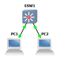
- Add an EtherSwitch router to a new GNS3 project.
- Add two VPCS PCs to the project.
- Add links to connect the following.
- PC1 Ethernet0 <-> ESW1 FastEthernet1/1.
- PC2 Ethernet0 <-> ESW1 FastEthernet1/2.
- Start the devices.
- Open the console for PC1. Set the IP address for PC1 using the following command.
ip 192.168.1.11 255.255.255.0 192.168.1.1
- Open the console for PC2. Set the IP address for PC2 using the following command.
ip 192.168.1.12 255.255.255.0 192.168.1.1
- Using the console for PC1, ping PC2 using the following command.
ping 192.168.1.12
- Using the console for PC2, ping PC1 using the following command.
ping 192.168.1.11
- If the pings are not successful, try replacing the EtherSwitch router with an Ethernet hub or switch and repeat the tests.


Lesson Summary
edit- GNS3 is a graphical network simulator supporting a variety of products from vendors including Alcatel-Lucent, Arista, Cisco, Extreme Networks, Fortigate, Juniper, Microtik, and Vyatta.[1]
- GNS3 is available for Windows, Linux, and macOS platforms.[2]
- The standard GNS3 Windows installation package includes WinPcap, Wireshark, Dynamips, QEMU, and VPCS Virtual PC Simulator.[3]
- WinPcap provides a packet-capture and filtering engine for Windows systems.[4]
- Libpcap provides a packet-capturing and filtering engine for Unix-like systems.[5]
- Wireshark is a free and open-source packet analyzer.[6]
- Dynamips is an emulator computer program that was created to emulate Cisco routers.[7]
- QEMU (Quick Emulator) is a free and open-source hosted hypervisor that performs hardware virtualization, and is used by GNS3 to run Cisco ASA, PIX and IDS, as well as conventional operating systems.[8][9]
- VPCS provides a simulated command-line interface for hosts connected to routers in a GNS3 / Dynamips network.[10]
- The GNS3 installation package does not include Cisco IOS images. IOS images must be loaded separately after GNS3 is installed.
- GNS3 cannot run Cisco switch IOS images, but does support EtherSwitch network modules to provide switching configurations on supported routers.[11]
- GNS3 support for EtherSwitch network modules includes Cisco routers from the 2600, 3600, and 3700 series.[12]
- The GNS3 user interface includes windows for node types, network topology, topology summary, and the Dynagen console for Dynamips.[13]
- Each IOS image must be loaded into GNS3 and configured with an Idle PC value before it can be used in a network topology.[14]
- After adding devices to a network topology, the devices must be started in order to access the device console.[15]
- Consoles are accessed through terminal emulation, Telnet, or SSH connections.[16]
- Network topologies may be saved and opened using the GNS3 File menu.[17]
Key Terms
edit- ping
- A computer network administration software utility used to test the reachability of a host on an Internet Protocol (IP) network and to measure the round-trip time for messages sent from the originating host to a destination computer and back.[18]
Review Questions
edit-
GNS3 is a graphical network simulator supporting a variety of products from vendors including _____.GNS3 is a graphical network simulator supporting a variety of products from vendors including Alcatel-Lucent, Arista, Cisco, Extreme Networks, Fortigate, Juniper, Microtik, and Vyatta.
-
GNS3 is available for _____ platforms.GNS3 is available for Windows, Linux, and macOS platforms.
-
The standard GNS3 Windows installation package includes _____.The standard GNS3 Windows installation package includes WinPcap, Wireshark, Dynamips, QEMU, and VPCS Virtual PC Simulator.
-
WinPcap provides _____.WinPcap provides a packet-capture and filtering engine for Windows systems.
-
Libpcap provides _____.Libpcap provides a packet-capturing and filtering engine for Unix-like systems.
-
Wireshark is _____.Wireshark is a free and open-source packet analyzer.
-
Dynamips is _____.Dynamips is an emulator computer program that was created to emulate Cisco routers.
-
QEMU (Quick Emulator) is _____.QEMU (Quick Emulator) is a free and open-source hosted hypervisor that performs hardware virtualization, and is used by GNS3 to run Cisco ASA, PIX and IDS, as well as conventional operating systems.
-
VPCS provides _____.VPCS provides a simulated command-line interface for hosts connected to routers in a GNS3 / Dynamips network.
-
The GNS3 installation package does not include _____.The GNS3 installation package does not include Cisco IOS images. IOS images must be loaded separately after GNS3 is installed.
-
GNS3 cannot run _____, but does support _____.GNS3 cannot run Cisco switch IOS images, but does support EtherSwitch network modules to provide switching configurations on supported routers.
-
GNS3 support for EtherSwitch network modules includes Cisco routers from the _____ series.GNS3 support for EtherSwitch network modules includes Cisco routers from the 2600, 3600, and 3700 series.
-
The GNS3 user interface includes windows for _____.The GNS3 user interface includes windows for node types, network topology, topology summary, and the Dynagen console for Dynamips.
-
Each IOS image must be loaded into GNS3 and configured with _____ before it can be used in a network topology.Each IOS image must be loaded into GNS3 and configured with an Idle PC value before it can be used in a network topology.
-
After adding devices to a network topology, the devices must be _____.After adding devices to a network topology, the devices must be started in order to access the device console.
-
Consoles are accessed through _____.Consoles are accessed through terminal emulation, Telnet, or SSH connections.
-
Network topologies may be saved and opened using _____.Network topologies may be saved and opened using the GNS3 File menu.
Assessments
edit- Flashcards: Quizlet: CCENT - Lab Setup
- Quiz: Quizlet: CCENT - Lab Setup
See Also
editReferences
edit- ↑ GNS3: List of Vendor Integrations
- ↑ GNS3: Download
- ↑ GNS3: Download
- ↑ Wikipedia: pcap
- ↑ Wikipedia: pcap
- ↑ Wikipedia: Wireshark
- ↑ Wikipedia: Dynamips
- ↑ Wikipedia: QEMU
- ↑ GNS3: Qemu
- ↑ SourceForge: VPCS
- ↑ GNS3: Switching Simulation
- ↑ GNS3: Hardware Emulated by GNS3
- ↑ SourceForge: GNS3 Tutorial
- ↑ SourceForge: GNS3 Tutorial
- ↑ SourceForge: GNS3 Tutorial
- ↑ SourceForge: GNS3 Tutorial
- ↑ SourceForge: GNS3 Tutorial
- ↑ Wikipedia: Ping (networking utility)
Lesson 6 - IOS Basics
editThis lesson covers basic router and switch configuration using IOS commands.
Objectives and Skills
editObjectives and skills for the IOS basics portion of Cisco CCENT certification include:[1]
- Configure and verify utilizing the CLI to set basic Router configuration
- Hostname
- banner
- motd
- Local user & password
- Enable secret password
- Console logins
- exec-timeout
- service password encryption
- copy run start
Readings
editMultimedia
editExamples
editGlobal Configuration
editenable
editTo enter privileged EXEC mode, or any other security level set by a system administrator, use the enable EXEC command.[2]
enable
disable
editTo exit privileged EXEC mode and return to user EXEC mode, or to exit to a lower privilege level, enter the disable EXEC command.[3]
disable
configure terminal
editTo enter global configuration mode, use the configure terminal command in privileged EXEC mode.[4]
configure terminal
exit
editTo exit any configuration mode to the next highest mode in the CLI mode hierarchy, use the exit command in any configuration mode. To close an active terminal session by logging off the router, use the exit command in EXEC mode.[5][6]
exit
hostname
editTo specify or modify the hostname for the network server, use the hostname command in global configuration mode.[7]
hostname <name>
ip domain-name
editTo configure the domain name server (DNS) domain name, use the ip domain-name command in global configuration mode.[8]
ip domain-name <domain-name>
banner login
editTo define and enable a customized banner to be displayed before the username and password login prompts, use the banner login global configuration command.[9]
banner login #<message>#
banner motd
editTo define and enable a message-of-the-day (MOTD) banner, use the banner motd global configuration command.[10]
banner motd #<message>#
Command Sequence
editA global configuration command sequence to enable privileged EXEC mode, enter global configuration mode, specify a hostname and banner messages, exit global configuration mode, disable privileged EXEC mode, and log off the router is:
enable
configure terminal
hostname router
ip domain-name example.com
banner login #Authorized users only!#
banner motd #System maintenance will occur on Friday!#
exit
disable
exit
Password Configuration
editline
editTo identify a specific line for configuration and enter line configuration collection mode, use the line command in global configuration mode.[11]
line console 0
password
editTo specify a password on a line, use the password command in line configuration mode.[12]
password <password>
login
editTo enable password checking at login, use the login command in line configuration mode.[13]
login
username
editTo establish a username-based authentication system, use the username command in global configuration mode.[14]
username <name> password <password>
login local
editTo enable username and password checking at login, use the login local command in line configuration mode.[15]
login local
exec-timeout
editTo set the interval that the EXEC command interpreter waits until user input is detected, use the exec-timeout line configuration command.[16]
exec-timeout <minutes>
enable password
editTo set a local clear-text password to control access to various privilege levels, use the enable password command in global configuration mode.[17]
enable password <password>
enable secret
editTo specify an additional layer of security over the enable password command, use the enable secret command in global configuration mode.[18]
enable secret <password>
service password-encryption
editTo encrypt passwords, use the service password-encryption command in global configuration mode.[19]
service password-encryption
Command Sequence
editA command sequence to configure passwords might be similar to the following.
enable
configure terminal

line console 0
password letmein
login
exit

enable secret cisco
service password-encryption
exit

show running-config
exit
A command sequence to configure usernames and passwords might be similar to the following.
enable
configure terminal

username admin1 password secret1
username admin2 password secret2

line console 0
login local
exit

enable secret cisco
service password-encryption
exit

show running-config
exit
Configuration Management
editshow running-config
editTo display the contents of the current running configuration file or the configuration for a specific module, Layer 2 VLAN, class map, interface, map class, policy map, or virtual circuit (VC) class, use the show running-config command in privileged EXEC mode.[20]
show running-config
show run
show startup-config
editThe show startup-config command displays the startup configuration file contained in NVRAM or specified by the CONFIG_FILE environment variable.[21]
show startup-config
show start
copy
editTo copy any file from a source to a destination, use the copy command in privileged EXEC or diagnostic mode.[22]
copy <source> <destination>
copy running-config startup-config
copy run start
erase
editTo erase a file system or all files available on a file system, use the erase command in privileged EXEC or diagnostic mode.[23]
erase {/all nvram: | file-system: | startup-config}
erase startup-config
reload
editTo reload the operating system, use the reload command in privileged EXEC or diagnostic mode.[24]
reload
Command Sequence
editA command sequence to manage device configuration might be similar to the following.
enable
show run
copy run start
show start
reload
Activities
edit- Connect to a Cisco router and practice using IOS commands.
- Review TechRepublic: 10 Commands You Should Master When Working with the Cisco IOS.
- Add a router to a new GNS3 project and start the device.
- Open the console for the router and practice using the following commands.
?show running-configshow interfaceshow ip interfaceshow ip interface briefshow ip routeshow version
- Configure a router hostname, banner login, and banner motd messages.
- Add a router to a new GNS3 project and start the device.
- Open the console for the router and practice using the following commands.
enableconfigure terminalhostnamebanner loginbanner motdexit
- Exit the router console session and open the console again to test the configuration.
- Configure router console password security.
- Add a router to a new GNS3 project and start the device.
- Open the console for the router and practice using the following commands.
enableconfigure terminalline console 0passwordloginexec-timeoutenable secretservice password-encryptionexit
- Verify the configuration using the following command.
show running-config
- Exit the router console session and open the console again to test the configuration.
- Configure router console username and password security.
- Add a router to a new GNS3 project and start the device.
- Open the console for the router and practice using the following commands.
enableconfigure terminalusernameline console 0login localexec-timeoutenable secretservice password-encryptionexit
- Verify the configuration using the following command.
show running-config
- Exit the router console session and open the console again to test the configuration.
- Manage router configuration.
- Use one or more of the router configurations above and manage the configuration using the following commands.
enableshow running-configcopy running-config startup-configshow startup-configreload
- After restarting the router, verify the configuration using the following command.
show running-config
- Clear the router configuration using the following commands.
erase startup-configreload
- After restarting the router, verify the configuration using the following command.
show running-config
- Use one or more of the router configurations above and manage the configuration using the following commands.
Lesson Summary
edit- Cisco IOS (originally Internetwork Operating System) is software used on most Cisco Systems routers and network switches.[25]
- IOS is a package of routing, switching, internetworking and telecommunications functions integrated into a multitasking operating system.[26]
- Cisco IOS command modes determine the commands and privilege level of the current user.[27]
- User EXEC mode allows connection to remote devices, changing terminal settings on a temporary basis, performing basic tests, and listing system information. User EXEC mode is indicated by a
Router>prompt.[28] - Privileged EXEC mode allows all EXEC commands available on the system. Privileged EXEC mode is indicated by a
Router#prompt.[29] - Global Configuration mode commands allow configuration of the system as a whole, and access to specific configuration modes and submodes. Global Configuration mode is indicated by a
Router(config)#prompt.[30] - ROM Monitor mode is used for system diagnostics or when a valid system image is not found. ROM Monitor mode is indicated by a
rommon1>prompt.[31] - Setup mode is an interactive sequence that allows first-time configuration of devices.[32]
- More than 100 detail configuration modes and submodes are available for different interfaces and protocols.[33]
- Almost every configuration command also has a
noform used to disable the feature or function.[34] - Context-sensitive help is available by entering
?in any command mode.[35] - To enter privileged EXEC mode, or any other security level set by a system administrator, use the
enableEXEC command.[36] - To exit privileged EXEC mode and return to user EXEC mode, or to exit to a lower privilege level, enter the
disableEXEC command.[37] - To enter global configuration mode, use the
configure terminalcommand in privileged EXEC mode.[38] - To exit any configuration mode to the next highest mode in the CLI mode hierarchy, use the
exitcommand in any configuration mode.[39] - To close an active terminal session by logging off the router, use the
exitcommand in EXEC mode.[40] - To specify or modify the hostname for the network server, use the
hostnamecommand in global configuration mode.[41] - To configure the domain name server (DNS) domain name, use the
ip domain-namecommand in global configuration mode.[42] - To define and enable a customized banner to be displayed before the username and password login prompts, use the
banner loginglobal configuration command.[43] - To define and enable a message-of-the-day (MOTD) banner, use the
banner motdglobal configuration command.[44] - To identify a specific line for configuration and enter line configuration collection mode, use the
linecommand in global configuration mode.[45] - To specify a password on a line, use the
passwordcommand in line configuration mode.[46] - To enable password checking at login, use the
logincommand in line configuration mode.[47] - To establish a username-based authentication system, use the
usernamecommand in global configuration mode.[48] - To enable username and password checking at login, use the
login localcommand in line configuration mode.[49] - To set the interval that the EXEC command interpreter waits until user input is detected, use the
exec-timeoutline configuration command.[50] - To set a local clear-text password to control access to various privilege levels, use the
enable passwordcommand in global configuration mode.[51] - To specify an additional layer of security over the enable password command, use the
enable secretcommand in global configuration mode.[52] - To encrypt passwords, use the
service password-encryptioncommand in global configuration mode.[53] - To display the contents of the current running configuration file or the configuration for a specific module, Layer 2 VLAN, class map, interface, map class, policy map, or virtual circuit (VC) class, use the
show running-configcommand in privileged EXEC mode.[54] - The
show startup-configcommand displays the startup configuration file contained in NVRAM or specified by the CONFIG_FILE environment variable.[55] - To copy any file from a source to a destination, use the
copycommand in privileged EXEC or diagnostic mode.[56] - To erase a file system or all files available on a file system, use the
erasecommand in privileged EXEC or diagnostic mode.[57] - To reload the operating system, use the
reloadcommand in privileged EXEC or diagnostic mode.[58]
Key Terms
edit- command-line interface (CLI)
- A means of interacting with a computer program where the user issues commands to the program in the form of successive lines of text.[59]
- configuration mode
- Allows commands that apply to the system as a whole, accessed using the
configurecommand.[60] - console
- The text entry and display interface for system administration messages.[61]
- enable mode
- Privileged EXEC mode, accessed using the
enablecommand.[62] - host name
- A label assigned to a device connected to a computer network and used to identify the device in various forms of electronic communication.[63]
- IOS image
- A Cisco system software file used to run Cisco routers and switches.[64]
- local username
- Usernames and passwords stored on the local device using the
login localandusernamecommands.[65] - running config file
- The current system configuration, stored in RAM.[66]
- startup config file
- The current system boot configuration, stored in NVRAM.[67]
- user mode
- User EXEC mode, accessed by logging into a device.[68]
Review Questions
edit-
Cisco IOS (originally _____) is _____.Cisco IOS (originally Internetwork Operating System) is software used on most Cisco Systems routers and network switches.
-
IOS is _____.IOS is a package of routing, switching, internetworking and telecommunications functions integrated into a multitasking operating system.
-
Cisco IOS command modes _____.Cisco IOS command modes determine the commands and privilege level of the current user.
-
User EXEC mode _____.User EXEC mode allows connection to remote devices, changing terminal settings on a temporary basis, performing basic tests, and listing system information.
-
User EXEC mode is indicated by _____.User EXEC mode is indicated by a Router> prompt.
-
Privileged EXEC mode _____.Privileged EXEC mode allows all EXEC commands available on the system.
-
Privileged EXEC mode is indicated by _____.Privileged EXEC mode is indicated by a Router# prompt.
-
Global Configuration mode commands _____.Global Configuration mode commands allow configuration of the system as a whole, and access to specific configuration modes and submodes.
-
Global Configuration mode is indicated by _____.Global Configuration mode is indicated by a Router(config)# prompt.
-
ROM Monitor mode is used for _____.ROM Monitor mode is used for system diagnostics or when a valid system image is not found.
-
ROM Monitor mode is indicated by _____.ROM Monitor mode is indicated by a rommon1> prompt.
-
Setup mode is _____.Setup mode is an interactive sequence that allows first-time configuration of devices.
-
More than 100 detail configuration modes and submodes are available for _____.More than 100 detail configuration modes and submodes are available for different interfaces and protocols.
-
Almost every configuration command also has _____ used to disable the feature or function.Almost every configuration command also has a no form used to disable the feature or function.
-
Context-sensitive help is available by _____.Context-sensitive help is available by entering ? in any command mode.
-
To enter privileged EXEC mode, or any other security level set by a system administrator, use _____.To enter privileged EXEC mode, or any other security level set by a system administrator, use the enable EXEC command.
-
To exit privileged EXEC mode and return to user EXEC mode, or to exit to a lower privilege level, use _____.To exit privileged EXEC mode and return to user EXEC mode, or to exit to a lower privilege level, use the disable EXEC command.
-
To enter global configuration mode, use _____.To enter global configuration mode, use the configure terminal command in privileged EXEC mode.
-
To exit any configuration mode to the next highest mode in the CLI mode hierarchy, use _____.To exit any configuration mode to the next highest mode in the CLI mode hierarchy, use the exit command in any configuration mode.
-
To close an active terminal session by logging off the router, use _____.To close an active terminal session by logging off the router, use the exit command in EXEC mode.
-
To specify or modify the hostname for the network server, use _____.To specify or modify the hostname for the network server, use the hostname command in global configuration mode.
-
To configure the domain name server (DNS) domain name, use _____.To configure the domain name server (DNS) domain name, use the ip domain-name command in global configuration mode.
-
To define and enable a customized banner to be displayed before the username and password login prompts, use _____.To define and enable a customized banner to be displayed before the username and password login prompts, use the banner login global configuration command.
-
To define and enable a message-of-the-day (MOTD) banner, use _____.To define and enable a message-of-the-day (MOTD) banner, use the banner motd global configuration command.
-
To identify a specific line for configuration and enter line configuration collection mode, use _____.To identify a specific line for configuration and enter line configuration collection mode, use the line command in global configuration mode.
-
To specify a password on a line, use _____.To specify a password on a line, use the password command in line configuration mode.
-
To enable password checking at login, use _____.To enable password checking at login, use the login command in line configuration mode.
-
To establish a username-based authentication system, use _____.To establish a username-based authentication system, use the username command in global configuration mode.
-
To enable username and password checking at login, use _____.To enable username and password checking at login, use the login local command in line configuration mode.
-
To set the interval that the EXEC command interpreter waits until user input is detected, use _____.To set the interval that the EXEC command interpreter waits until user input is detected, use the exec-timeout line configuration command.
-
To set a local clear-text password to control access to various privilege levels, use _____.To set a local clear-text password to control access to various privilege levels, use the enable password command in global configuration mode.
-
To specify an additional layer of security over the enable password command, use _____.To specify an additional layer of security over the enable password command, use the enable secret command in global configuration mode.
-
To encrypt passwords, use _____.To encrypt passwords, use the service password-encryption command in global configuration mode.
-
To display the contents of the current running configuration file or the configuration for a specific module, Layer 2 VLAN, class map, interface, map class, policy map, or virtual circuit (VC) class, use _____.To display the contents of the current running configuration file or the configuration for a specific module, Layer 2 VLAN, class map, interface, map class, policy map, or virtual circuit (VC) class, use the show running-config command in privileged EXEC mode.
-
The show startup-config command _____.The show startup-config command displays the startup configuration file contained in NVRAM or specified by the CONFIG_FILE environment variable.
-
To copy any file from a source to a destination, use _____.To copy any file from a source to a destination, use the copy command in privileged EXEC or diagnostic mode.
-
To erase a file system or all files available on a file system, use _____.To erase a file system or all files available on a file system, use the erase command in privileged EXEC or diagnostic mode.
-
To reload the operating system, use _____.To reload the operating system, use the reload command in privileged EXEC or diagnostic mode.
Assessments
edit- Flashcards: Quizlet: CCENT - IOS Basics
- Quiz: Quizlet: CCENT - Lab Setup
See Also
editReferences
edit- ↑ Cisco: ICND1 Exam Topics
- ↑ Cisco: Basic Command-Line Interface Commands
- ↑ Cisco: Basic Command-Line Interface Commands
- ↑ Cisco: IOS Configuration Fundamentals Command Reference
- ↑ Cisco: IOS Configuration Fundamentals Command Reference
- ↑ Cisco: IOS Configuration Fundamentals Command Reference
- ↑ Cisco: IOS Configuration Fundamentals Command Reference
- ↑ Cisco: Unity Express 2.0 Command Reference
- ↑ Cisco: IOS Configuration Fundamentals Command Reference
- ↑ Cisco: IOS Configuration Fundamentals Command Reference
- ↑ Cisco: Cisco IOS Terminal Services Command Reference
- ↑ Cisco: Passwords and Privileges
- ↑ Cisco IOS Terminal Services Command Reference
- ↑ Cisco: Passwords and Privileges Commands
- ↑ Cisco: Telnet, Console and AUX Port Passwords on Cisco Routers Configuration Example
- ↑ Cisco: IOS Configuration Fundamentals Command Reference
- ↑ Cisco: Passwords and Privileges Commands
- ↑ Cisco: Passwords and Privileges Commands
- ↑ Cisco: Passwords and Privileges Commands
- ↑ Cisco: IOS Configuration Fundamentals Command Reference
- ↑ Cisco: IOS Configuration Fundamentals Command Reference
- ↑ Cisco: IOS Configuration Fundamentals Command Reference
- ↑ Cisco: IOS Configuration Fundamentals Command Reference
- ↑ Cisco: IOS Configuration Fundamentals Command Reference
- ↑ Wikipedia: Cisco IOS
- ↑ Wikipedia: Cisco IOS
- ↑ Wikipedia: Cisco IOS
- ↑ Cisco: IOS Command Modes
- ↑ Cisco: IOS Command Modes
- ↑ Cisco: IOS Command Modes
- ↑ Cisco: IOS Command Modes
- ↑ Cisco: IOS Command Modes
- ↑ Cisco: IOS Command Modes
- ↑ Cisco: IOS and Configuration Basics
- ↑ Cisco: IOS and Configuration Basics
- ↑ Cisco: Basic Command-Line Interface Commands
- ↑ Cisco: Basic Command-Line Interface Commands
- ↑ Cisco: IOS Configuration Fundamentals Command Reference
- ↑ Cisco: IOS Configuration Fundamentals Command Reference
- ↑ Cisco: IOS Configuration Fundamentals Command Reference
- ↑ Cisco: IOS Configuration Fundamentals Command Reference
- ↑ Cisco: Unity Express 2.0 Command Reference
- ↑ Cisco: IOS Configuration Fundamentals Command Reference
- ↑ Cisco: IOS Configuration Fundamentals Command Reference
- ↑ Cisco: Cisco IOS Terminal Services Command Reference
- ↑ Cisco: Passwords and Privileges
- ↑ Cisco IOS Terminal Services Command Reference
- ↑ Cisco: Passwords and Privileges Commands
- ↑ Cisco: Telnet, Console and AUX Port Passwords on Cisco Routers Configuration Example
- ↑ Cisco: IOS Configuration Fundamentals Command Reference
- ↑ Cisco: Passwords and Privileges Commands
- ↑ Cisco: Passwords and Privileges Commands
- ↑ Cisco: Passwords and Privileges Commands
- ↑ Cisco: IOS Configuration Fundamentals Command Reference
- ↑ Cisco: IOS Configuration Fundamentals Command Reference
- ↑ Cisco: IOS Configuration Fundamentals Command Reference
- ↑ Cisco: IOS Configuration Fundamentals Command Reference
- ↑ Cisco: IOS Configuration Fundamentals Command Reference
- ↑ Wikipedia: Command-line interface
- ↑ Cisco: IOS Command Reference
- ↑ Wikipedia: System console
- ↑ Cisco: IOS Command Reference
- ↑ Wikipedia: Hostname
- ↑ Wikipedia: Cisco IOS
- ↑ Cisco: Telnet, Console and AUX Port Passwords on Cisco Routers Configuration Example
- ↑ Cisco: IOS and Configuration Basics
- ↑ Cisco: IOS and Configuration Basics
- ↑ Cisco: IOS and Configuration Basics
Lesson 7 - Network Services
editThis lesson covers network services, including DHCP, DNS, NTP, and NAT.
Objectives and Skills
editObjectives and skills for the network services portion of Cisco CCENT certification include:[1]
- Configure and verify DHCP (IOS router)
- Configuring router interfaces to use DHCP
- DHCP options (Basic overview and functionality)
- Excluded addresses
- Lease time
- Configure and verify NTP as a client
- Identify the basic operation of NAT
- Purpose
- Pool
- Static
- 1 to 1
- Overloading
- Source addressing
- One-way NAT
- Configure and verify NAT for given network requirements
Readings
edit- Wikipedia: Dynamic Host Configuration Protocol
- Wikipedia: DHCPv6
- Wikipedia: Domain Name System
- Wikipedia: Network Time Protocol
- Wikipedia: Network address translation
- Cisco: Configuring the Cisco IOS DHCP Client
- Cisco: Configuring DNS on Cisco Routers
- Cisco: Configuring Network Address Translation
- Networking Signal: DHCP Dora Process
Multimedia
edit- YouTube: DHCP Addressing Overview - CompTIA Network+ N10-005: 2.3
- YouTube: An Overview of DNS - CompTIA Network+ N10-005: 1.7
- YouTube: Configuring a DHCP Server on a Cisco Router
- YouTube: Configuring NAT (PAT) on Cisco Routers
- Cisco: Internet Connections with NAT and PAT
- YouTube: GNS3 Tutorial - Connecting GNS3 Routers to the Internet in Windows 7
Examples
editDHCP Client Configuration
editip address dhcp
editTo assign a dynamic IP address to an interface, use the ip address dhcp command.[2]
ip address dhcp
release dhcp
editTo release a dynamic IP address, use the release dhcp command.[3]
release dhcp <interface>
renew dhcp
editTo renew a dynamic IP address, use the renew dhcp command.[4]
renew dhcp <interface>
Command Sequence
editA command sequence to assign a dynamic ip address would be similar to the following.
enable
configure terminal
interface fastethernet0/1
ip address dhcp
no shutdown
exit
exit

show ip interface brief

exit
A command sequence to release and renew a dynamic ip address would be similar to the following.
enable
release dhcp fastethernet0/1
show ip interface brief

renew dhcp fastethernet0/1
show ip interface brief

exit
DNS Configuration
editip domain lookup
editTo enable IP Domain Name System (DNS)-based hostname-to-address translation, use the ip domain lookup command in global configuration mode.[5]
ip domain lookup
ip name-server
editTo specify one or more hosts (up to six) that can function as a name server to supply name information for the DNS, use the ip name-server command in global configuration mode.[6]
ip name-server <ip address> [<ip address>] [<ip address>] [<ip address>] [<ip address>] [<ip address>]
ip dns server
editTo enable the Domain Name System (DNS) server on a router, use the ip dns server command in global configuration mode.[7]
ip dns server
Command Sequence
editA command sequence to configure the DNS service and verify DNS host name lookup would be similar to the following.
enable
configure terminal
ip domain lookup
ip name-server 8.8.8.8 8.8.4.4
ip dns server
exit

ping en.wikiversity.org
exit
DHCP Server Configuration
editip dhcp excluded-address
editTo specify the IP addresses that the DHCP Server should not assign to clients, use the ip dhcp excluded-address command in global configuration mode.[8]
ip dhcp excluded-address <start> <end>
ip dhcp pool
editTo configure the DHCP address pool name and enter DHCP pool configuration mode, use the ip dhcp pool command in global configuration mode.[9]
ip dhcp pool <name>
network
editTo configure a subnet and mask for the newly created DHCP address pool, use the network command in DHCP pool configuration mode.[10]
network <network> [<mask> | </prefix>]
default-router
editTo specify a default router for a DHCP client, use the default-router command in DHCP pool configuration mode.[11]
default-router <address> [<address2>] ... [<address8>]
domain-name
editTo configure a domain name string for the client, use the domain-name command in DHCP pool configuration mode.[12]
domain-name <domain>
dns-server
editTo configure the DNS IP servers that are available to a DHCP client, use the dns-server command in DHCP pool configuration mode.[13]
dns-server <address> [<address2>] ... [<address8>]
lease
editBy default, each IP address assigned by a DHCP Server comes with a one-day lease. To change the lease value, use the lease command in DHCP pool configuration mode. [14]
lease [<days> [<hours>] [<minutes>] | infinite]
show ip dhcp
editTo display DHCP Server information, use the following commands in EXEC mode, as needed:
show ip dhcp pool <name>
show ip dhcp binding
show ip dhcp server statistics
Command Sequence
editA command sequence to configure a DHCP server would be similar to the following.
enable
configure terminal
ip dhcp excluded-address 192.168.1.1 192.168.1.10
ip dhcp pool local
network 192.168.1.0 255.255.255.0
default-router 192.168.1.1
domain-name example.com
dns-server 192.168.1.1
lease 1
exit
exit

show ip dhcp pool local
show ip dhcp binding
show ip dhcp server statistics
exit
NTP Configuration
editshow clock
editTo display the time and date from the system software clock, use the show clock EXEC command.[15]
show clock
ntp server
editTo allow the software clock to be synchronized by a Network Time Protocol (NTP) time server, use the ntp server command in global configuration mode.[16]
ntp server <ip address> | <hostname>
show ntp associations
editTo show the status of Network Time Protocol (NTP) associations, use the show ntp associations EXEC command.[17]
show ntp associations
Command Sequence
editA command sequence to configure and verify an NTP server would be similar to the following.
enable
show clock

configure terminal
ip domain lookup
ntp server us.pool.ntp.org
exit

show clock
show ntp associations
exit
NAT Configuration
editip nat
editTo designate that traffic originating from or destined for the interface is subject to Network Address Translation ( NAT), use the ip nat command in interface configuration mode.[18]
ip nat <inside | outside>
ip nat inside
ip nat outside
ip nat inside source
editTo enable Network Address Translation (NAT) of the inside source address, use the ip nat inside source command in global configuration mode.[19]
Static NAT
ip nat inside source static <local-ip> <global-ip>
ip nat inside source static 192.168.1.11 10.11.22.33

Port Static NAT
ip nat inside source static <tcp | udp> <local-ip> <local-port> <global-ip> <global-port>
ip nat inside source static tcp 192.168.1.11 80 172.16.11.1 80

Dynamic NAT
ip nat inside source list <access-list-number> interface <interface> [overload]
ip nat inside source list 1 interface FastEthernet0/1 overload

Dynamic NAT Pool
ip nat inside source list <access-list-number> pool <name>
ip nat inside source list 1 pool global
ip nat pool
editTo define a pool of IP addresses for Network Address Translation (NAT) translations, use the ip nat pool command in global configuration mode.[20]
ip nat pool <name> <start-ip> <end-ip> netmask <netmask>
ip nat pool <name> <start-ip> <end-ip> prefix-length <prefix-length>
ip nat pool global 10.11.22.33 10.11.22.38 netmask 255.255.255.248
ip nat pool global 10.11.22.33 10.11.22.38 prefix-length 29
access list
editTo define a standard IP access list, use the standard version of the access-list command in global configuration mode.[21]
access-list <access-list-number> <deny | permit> <source> <source-wildcard>
access-list 1 permit 192.168.1.0 0.0.0.255
Command Sequence
editA command sequence to configure dynamic NAT/PAT would be similar to the following.
enable
configure terminal

interface FastEthernet0/0
ip address 192.168.1.1 255.255.255.0
ip nat inside
exit

interface FastEthernet0/1
ip address dhcp
ip nat outside
exit

ip nat inside source list 1 interface FastEthernet0/1 overload
access-list 1 permit 192.168.1.0 0.0.0.255
exit

show running-config
exit
Activities
edit- Configure dynamic client addressing.

- Add a cloud and a router to a new GNS3 project and start the devices.
- Configure the cloud and add a Generic Ethernet NIO interface matching your host computer's Ethernet interface.
- Add a link to connect the following.
- R1 FastEthernet0/1 <-> Cloud1 Ethernet connection
- Open the console for the router and practice using the following commands.
enableconfigure terminalinterfaceip address dhcpno shutdownexit
- Verify the configuration using the following commands.
show ip interface briefshow ip default-gateway
- Configure host name resolution.
- Use the router from above and practice using the following commands.
enableconfigure terminalip domain lookupip name-serverip dns serverexit
- Verify the configuration using the following command.
ping en.wikiversity.org.
- Use the router from above and practice using the following commands.
- Configure an NTP server.
- Use the router from above and practice using the following commands.
enableshow clockconfigure terminalntp serverexit
- Verify the configuration using the following commands.
show ntp associations.show clock.
- Use the router from above and practice using the following commands.
- Configure a router as a DHCP server.

- Use the router from above and practice using the following commands.
enableconfigure terminalip dhcp excluded-addressip dhcp pool localnetworkdefault-routerdomain-namedns-serverleaseexit
- Verify the configuration using the following commands.
show ip dhcp pool localshow ip dhcp bindingshow ip dhcp server statistics
- Test the configuration by adding a VCPS PC to the project.
- Add a link to connect the following.
- R1 FastEthernet0/0 <-> PC1 Ethernet0
- Open the console for PC1. Set the IP address for PC1 using the following commands.
ip dhcpping
- Use the router from above and practice using the following commands.
- Configure a router to provide NAT/PAT.
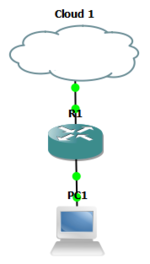
- Use the router and PC from above and practice using the following commands.
enableconfigure terminalinterfaceip nataccess-listip nat inside sourceexit
- Verify the configuration using the following commands.
show running-config
- Open the console for PC1 and test the configuration using the following command.
ping 8.8.8.8
- Use the router and PC from above and practice using the following commands.


Lesson Summary
edit- Dynamic Host Configuration Protocol is used by hosts to request Internet Protocol parameters from a network server.[22]
- DHCPv4 operations fall into four basic phases: IP discovery, IP lease offer, IP request, and IP lease acknowledgement. These points are often abbreviated as DORA (Discovery, Offer, Request, Acknowledgement).[23]
- DHCPv4 options provided to clients include subnet mask, router (default gateway), domain name server, domain name, lease time, renewal time (T1), rebinding time (T2), and others.[24]
- Network links without a DHCP server can use DHCP relay agents to receive messages from DHCP clients and forward them to DHCP servers. DHCP servers send responses back to the relay agent, and the relay agent then sends these responses to the DHCP client on the local network link.[25]
- DHCPv6 operations are similar to DHCPv4, but are described as Solicit, Advertise, Request, and Reply.[26] Renewals are processed with Renew and Reply.[27]
- Domain Name System (DNS) is a hierarchical distributed naming system for computers, services, or any resource connected to the Internet or a private network.[28]
- DNS distributes the responsibility of assigning domain names and mapping those names to IP addresses. Authoritative name servers are assigned to be responsible for their particular domains, and in turn can assign other authoritative name servers for their sub-domains.[29]
- Caching DNS servers cache DNS queries and perform recursive queries to improve efficiency, reduce DNS traffic across the Internet, and increase performance in end-user applications.[30]
- Network Time Protocol (NTP) is a networking protocol for clock synchronization between computer systems over packet-switched, variable-latency data networks.[31]
- NTP is intended to synchronize all participating computers to within a few milliseconds of Coordinated Universal Time (UTC).[32]
- Network address translation (NAT) is a methodology of remapping one IP address space into another by modifying network address information in Internet Protocol (IP) datagram packet headers while they are in transit across a traffic routing device.[33]
- To assign a dynamic IP address to an interface, use the
ip address dhcpcommand.[34] - To release a dynamic IP address, use the
release dhcpcommand.[35] - To renew a dynamic IP address, use the
renew dhcpcommand.[36] - To enable IP Domain Name System (DNS)-based hostname-to-address translation, use the
ip domain lookupcommand in global configuration mode.[37] - To specify one or more hosts (up to six) that can function as a name server to supply name information for the DNS, use the
ip name-servercommand in global configuration mode.[38] - To enable the Domain Name System (DNS) server on a router, use the
ip dns servercommand in global configuration mode.[39] - To specify the IP addresses that the DHCP Server should not assign to clients, use the
ip dhcp excluded-addresscommand in global configuration mode.[40] - To configure the DHCP address pool name and enter DHCP pool configuration mode, use the
ip dhcp poolcommand in global configuration mode.[41] - To configure a subnet and mask for the newly created DHCP address pool, use the
networkcommand in DHCP pool configuration mode.[42] - To specify a default router for a DHCP client, use the
default-routercommand in DHCP pool configuration mode.[43] - To configure a domain name string for the client, use the
domain-namecommand in DHCP pool configuration mode.[44] - To configure the DNS IP servers that are available to a DHCP client, use the
dns-servercommand in DHCP pool configuration mode.[45] - To change the default DHCP lease value, use the
leasecommand in DHCP pool configuration mode.[46] - To display DHCP Server information, use the commands
show ip dhcp pool <name>,show ip dhcp binding, andshow ip dhcp server statisticsin EXEC mode, as needed. - To display the time and date from the system software clock, use the
show clockEXEC command.[47] - To allow the software clock to be synchronized by a Network Time Protocol (NTP) time server, use the
ntp servercommand in global configuration mode.[48] - To show the status of Network Time Protocol (NTP) associations, use the
show ntp associationsEXEC command.[49] - To designate that traffic originating from or destined for the interface is subject to Network Address Translation ( NAT), use the
ip natcommand in interface configuration mode.[50] - To enable Network Address Translation (NAT) of the inside source address, use the
ip nat inside sourcecommand in global configuration mode.[51] - To define a pool of IP addresses for Network Address Translation (NAT) translations, use the
ip nat poolcommand in global configuration mode.[52] - To define a standard IP access list, use the standard version of the
access-listcommand in global configuration mode.[53]
Key Terms
edit- inside global
- A legitimate IP address assigned by the NIC or service provider that represents one or more inside local IP addresses to the outside world.[54]
- inside local
- The IP address assigned to a host on the inside network.[55]
- NAT overload
- Allows NAT to translate multiple inside devices to a single address in the pool.[56]
- outside global
- The IP address assigned to a host on the outside network by the host owner.[57]
- outside local
- The IP address of an outside host as it appears to the inside network.[58]
- PAT
- Address translation using only one or a few external addresses to support multiple internal addresses. Also see NAT overload.[59]
- stateful DHCPv6
- Enables DHCP servers to pass configuration parameters, such as IPv6 network addresses, to IPv6 nodes.[60]
- stateless DHCPv6
- Uses stateless autoconfiguration (SLAAC) to assign one or more IPv6 addresses to an interface, while it utilizes DHCPv6 to receive additional parameters which may not be available through SLAAC.[61]
- Stateless Address Autoconfiguration (SLAAC)
- A method by which a node automatically creates a link-local address with the prefix fe80::/64 on each IPv6-enabled interface, even if globally routable addresses are manually configured or obtained through configuration protocols.[62]
Review Questions
edit-
Dynamic Host Configuration Protocol is used by hosts to _____.Dynamic Host Configuration Protocol is used by hosts to request Internet Protocol parameters from a network server.
-
DHCPv4 operations fall into four basic phases: _____. These points are often abbreviated as _____.DHCPv4 operations fall into four basic phases: IP discovery, IP lease offer, IP request, and IP lease acknowledgement. These points are often abbreviated as DORA (Discovery, Offer, Request, Acknowledgement).
-
DHCPv4 options provided to clients include _____.DHCPv4 options provided to clients include subnet mask, router (default gateway), domain name server, domain name, lease time, renewal time (T1), rebinding time (T2), and others.
-
Network links without a DHCP server can use _____ to receive messages from DHCP clients and forward them to DHCP servers.Network links without a DHCP server can use DHCP relay agents to receive messages from DHCP clients and forward them to DHCP servers. DHCP servers send responses back to the relay agent, and the relay agent then sends these responses to the DHCP client on the local network link.
-
DHCPv6 operations are similar to DHCPv4, but are described as _____.DHCPv6 operations are similar to DHCPv4, but are described as Solicit, Advertise, Request, and Reply.[26] Renewals are processed with Renew and Reply.
-
Domain Name System (DNS) is _____.Domain Name System (DNS) is a hierarchical distributed naming system for computers, services, or any resource connected to the Internet or a private network.
-
DNS distributes _____. Authoritative name servers are _____.DNS distributes the responsibility of assigning domain names and mapping those names to IP addresses. Authoritative name servers are assigned to be responsible for their particular domains, and in turn can assign other authoritative name servers for their sub-domains.
-
Caching DNS servers _____.Caching DNS servers cache DNS queries and perform recursive queries to improve efficiency, reduce DNS traffic across the Internet, and increase performance in end-user applications.
-
Network Time Protocol (NTP) is _____.Network Time Protocol (NTP) is a networking protocol for clock synchronization between computer systems over packet-switched, variable-latency data networks.
-
NTP is intended to synchronize all participating computers to _____.NTP is intended to synchronize all participating computers to within a few milliseconds of Coordinated Universal Time (UTC).
-
Network address translation (NAT) is _____.Network address translation (NAT) is a methodology of remapping one IP address space into another by modifying network address information in Internet Protocol (IP) datagram packet headers while they are in transit across a traffic routing device.
-
To assign a dynamic IP address to an interface, use _____.To assign a dynamic IP address to an interface, use the ip address dhcp command.
-
To release a dynamic IP address, use _____.To release a dynamic IP address, use the release dhcp command.
-
To renew a dynamic IP address, use _____.To renew a dynamic IP address, use the renew dhcp command.
-
To enable IP Domain Name System (DNS)-based hostname-to-address translation, use _____.To enable IP Domain Name System (DNS)-based hostname-to-address translation, use the ip domain lookup command in global configuration mode.
-
To specify one or more hosts (up to six) that can function as a name server to supply name information for the DNS, use _____.To specify one or more hosts (up to six) that can function as a name server to supply name information for the DNS, use the ip name-server command in global configuration mode.
-
To enable the Domain Name System (DNS) server on a router, use _____.To enable the Domain Name System (DNS) server on a router, use the ip dns server command in global configuration mode.
-
To specify the IP addresses that the DHCP Server should not assign to clients, use _____.To specify the IP addresses that the DHCP Server should not assign to clients, use the ip dhcp excluded-address command in global configuration mode.
-
To configure the DHCP address pool name and enter DHCP pool configuration mode, use _____.To configure the DHCP address pool name and enter DHCP pool configuration mode, use the ip dhcp pool command in global configuration mode.
-
To configure a subnet and mask for the newly created DHCP address pool, use _____.To configure a subnet and mask for the newly created DHCP address pool, use the network command in DHCP pool configuration mode.
-
To specify a default router for a DHCP client, use _____.To specify a default router for a DHCP client, use the default-router command in DHCP pool configuration mode.
-
To configure a domain name string for the client, use _____.To configure a domain name string for the client, use the domain-name command in DHCP pool configuration mode.
-
To configure the DNS IP servers that are available to a DHCP client, use _____.To configure the DNS IP servers that are available to a DHCP client, use the dns-server command in DHCP pool configuration mode.
-
To change the default DHCP lease value, use _____.To change the default DHCP lease value, use the lease command in DHCP pool configuration mode.
-
To display DHCP Server information, use the commands _____, _____, and _____ in EXEC mode, as needed.To display DHCP Server information, use the commands show ip dhcp pool <name>, show ip dhcp binding, and show ip dhcp server statistics in EXEC mode, as needed.
-
To display the time and date from the system software clock, use _____.To display the time and date from the system software clock, use the show clock EXEC command.
-
To allow the software clock to be synchronized by a Network Time Protocol (NTP) time server, use _____.To allow the software clock to be synchronized by a Network Time Protocol (NTP) time server, use the ntp server command in global configuration mode.
-
To show the status of Network Time Protocol (NTP) associations, use _____.To show the status of Network Time Protocol (NTP) associations, use the show ntp associations EXEC command.
-
To designate that traffic originating from or destined for the interface is subject to Network Address Translation ( NAT), use _____.To designate that traffic originating from or destined for the interface is subject to Network Address Translation ( NAT), use the ip nat command in interface configuration mode.
-
To enable Network Address Translation (NAT) of the inside source address, use _____.To enable Network Address Translation (NAT) of the inside source address, use the ip nat inside source command in global configuration mode.
-
To define a pool of IP addresses for Network Address Translation (NAT) translations, use _____.To define a pool of IP addresses for Network Address Translation (NAT) translations, use the ip nat pool command in global configuration mode.
-
To define a standard IP access list, use _____.To define a standard IP access list, use the standard version of the access-list command in global configuration mode.
Assessments
edit- Flashcards: Quizlet: CCENT - Network Services
- Quiz: Quizlet: CCENT - Network Services
See Also
editReferences
edit- ↑ Cisco: ICND1 Exam Topics
- ↑ Cisco: Configuring the Cisco IOS DHCP Client
- ↑ Cisco: Configuring the Cisco IOS DHCP Client
- ↑ Cisco: Configuring the Cisco IOS DHCP Client
- ↑ Cisco: IOS IP Addressing Services Command Reference
- ↑ Cisco: IOS IP Configuration Guide
- ↑ Cisco: IOS Network Management Command Reference
- ↑ Cisco: Configuring DHCP
- ↑ Cisco: Configuring DHCP
- ↑ Cisco: Configuring DHCP
- ↑ Cisco: Configuring DHCP
- ↑ Cisco: Configuring DHCP
- ↑ Cisco: Configuring DHCP
- ↑ Cisco: Configuring DHCP
- ↑ Cisco: IOS Configuration Fundamentals Command Reference
- ↑ Cisco: IOS Configuration Fundamentals Command Reference
- ↑ Cisco: IOS Configuration Fundamentals Command Reference
- ↑ Cisco: IOS IP Addressing Services Command Reference
- ↑ Cisco: IOS IP Addressing Services Command Reference
- ↑ Cisco: IOS IP Addressing Services Command Reference
- ↑ Cisco: IOS IP Command Reference
- ↑ Wikipedia: Dynamic Host Configuration Protocol
- ↑ Wikipedia: Dynamic Host Configuration Protocol
- ↑ Wikipedia: Dynamic Host Configuration Protocol
- ↑ Wikipedia: Dynamic Host Configuration Protocol
- ↑ Wikipedia: DHCPv6
- ↑ RFC 3315
- ↑ Wikipedia: Domain Name System
- ↑ Wikipedia: Domain Name System
- ↑ Wikipedia: Domain Name System#Recursive and caching name server
- ↑ Wikipedia: Network Time Protocol
- ↑ Wikipedia: Network Time Protocol
- ↑ Wikipedia: Network address translation
- ↑ Cisco: Configuring the Cisco IOS DHCP Client
- ↑ Cisco: Configuring the Cisco IOS DHCP Client
- ↑ Cisco: Configuring the Cisco IOS DHCP Client
- ↑ Cisco: IOS IP Addressing Services Command Reference
- ↑ Cisco: IOS IP Configuration Guide
- ↑ Cisco: IOS Network Management Command Reference
- ↑ Cisco: Configuring DHCP
- ↑ Cisco: Configuring DHCP
- ↑ Cisco: Configuring DHCP
- ↑ Cisco: Configuring DHCP
- ↑ Cisco: Configuring DHCP
- ↑ Cisco: Configuring DHCP
- ↑ Cisco: Configuring DHCP
- ↑ Cisco: IOS Configuration Fundamentals Command Reference
- ↑ Cisco: IOS Configuration Fundamentals Command Reference
- ↑ Cisco: IOS Configuration Fundamentals Command Reference
- ↑ Cisco: IOS IP Addressing Services Command Reference
- ↑ Cisco: IOS IP Addressing Services Command Reference
- ↑ Cisco: IOS IP Addressing Services Command Reference
- ↑ Cisco: IOS IP Command Reference
- ↑ Cisco: NAT Local and Global Definitions
- ↑ Cisco: NAT Local and Global Definitions
- ↑ Cisco: Configuring Network Address Translation
- ↑ Cisco: NAT Local and Global Definitions
- ↑ Cisco: NAT Local and Global Definitions
- ↑ Cisco: IOS Network Address Translation Overivew
- ↑ Cisco DHCPv6 Based IPv6 Access Services
- ↑ Cisco DHCPv6 Based IPv6 Access Services
- ↑ Wikipedia: IPv6 address#Stateless address autoconfiguration
Lesson 8 - Static Routing
editThis lesson covers static routing.
Objectives and Skills
editObjectives and skills for the routing portion of Cisco CCENT certification include:[1]
- Describe basic routing concepts
- Packet forwarding
- Router lookup process
- Process Switching/Fast Switching/CEF
- Configure and verify operation status of an Ethernet interface
- Verify router configuration and network connectivity using
- ping
- Extended ping
- traceroute
- telnet
- SSH
- Show cdp neighbors
- ping
- Configure and verify routing configuration for a static or default route given specific routing requirements
Readings
editMultimedia
editExamples
editStatic Routing Configuration
editshow ip route
editTo display the current state of the routing table, use the show ip route command in user EXEC or privileged EXEC mode.[2]
show ip route [ip-address]
show ip route
show arp
editTo display the entries in the Address Resolution Protocol (ARP) table, use the show arp command in user EXEC or privileged EXEC mode.[3]
show arp
ip route
editTo establish static routes, use the ip route command in global configuration mode. To remove static routes, use the no form of this command.[4]
ip route prefix mask <ip-address | interface-type interface-number> [permanent]
ip route 192.168.3.0 255.255.255.0 192.168.2.2
trace / traceroute
editTo discover the routes that packets will actually take when traveling to their destination, use the trace / traceroute privileged EXEC command.[5]
trace <destination>
trace 8.8.8.8
traceroute 8.8.8.8
show cdp neighbors
editTo display detailed information about neighboring devices discovered using Cisco Discovery Protocol (CDP), use the show cdp neighbors privileged EXEC command.[6]
show cdp neighbors
show cdp neighbors detail
Command Sequence
editA command sequence to configure static routing might be similar to the following. Routing must typically be configured on source, intermediate, and destination network routers for responses to be received.
enable
configure terminal

ip route 192.168.3.0 255.255.255.0 192.168.2.2
exit

show ip route
ping 192.168.3.1
trace 192.168.3.1

exit
Activities
edit- Complete the Cisco Basic IP Routing Concepts training tutorial.
- Observe and test connected routes.
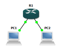
- Add one router and two VPCS PCs to a new GNS3 project.
- Add links to connect the following.
- PC1 Ethernet0 <-> R1 FastEthernet0/0
- PC2 Ethernet0 <-> R1 FastEthernet0/1
- Start the devices.
- Set the following IP addresses, subnet masks, and for the PCs, default gateways
- R1 FastEthernet0/0: 192.168.1.1 255.255.255.0
- R1 FastEthernet0/1: 192.168.2.1 255.255.255.0
- PC1 Ethernet0: 192.168.1.11 255.255.255.0 192.168.1.1
- PC2 Ethernet0: 192.168.2.11 255.255.255.0 192.168.2.1
- Display the routing table using the following command.
show ip route
- Test the configuration using the following commands from the router and the PCs. Test all router and PC addresses. All tests should be successful.
pingtrace
- Configure and test static routes.

- Add two routers and two VPCS PCs to a new GNS3 project.
- Add links to connect the following.
- PC1 Ethernet0 <-> R1 FastEthernet0/0
- R1 FastEthernet0/1 <-> R2 FastEthernet0/0
- PC2 Ethernet0 <-> R2 FastEthernet0/1
- Start the devices.
- Set the following IP addresses, subnet masks, and for the PCs, default gateways
- R1 FastEthernet0/0: 192.168.1.1 255.255.255.0
- R1 FastEthernet0/1: 192.168.2.1 255.255.255.0
- R2 FastEthernet0/0: 192.168.2.2 255.255.255.0
- R2 FastEthernet0/1: 192.168.3.1 255.255.255.0
- PC1 Ethernet0: 192.168.1.11 255.255.255.0 192.168.1.1
- PC2 Ethernet0: 192.168.3.11 255.255.255.0 192.168.3.1
- Display the routing tables using the following command.
show ip route
- Test the configuration using the following commands from the routers and the PCs. Test all router and PC addresses. Only the connected routes should be successful.
pingtrace
- Add static routes using the following commands.
- R1:
ip route 192.168.3.0 255.255.255.0 192.168.2.2 - R2:
ip route 192.168.1.0 255.255.255.0 192.168.2.1
- R1:
- Display the routing tables using the following command.
show ip route
- Test the configuration using the following commands from the routers and the PCs. Test all router and PC addresses. All tests should be successful.
pingtrace
- Configure and test default routes.

- Add three routers and two VPCS PCs to a new GNS3 project.
- Add links to connect the following.
- PC1 Ethernet0 <-> R1 FastEthernet0/0
- R1 FastEthernet0/1 <-> R2 FastEthernet0/0
- R2 FastEthernet0/1 <-> R3 FastEthernet0/0
- PC2 Ethernet0 <-> R3 FastEthernet0/1
- Start the devices.
- Set the following IP addresses, subnet masks, and for the PCs, default gateways
- R1 FastEthernet0/0: 192.168.1.1 255.255.255.0
- R1 FastEthernet0/1: 192.168.2.1 255.255.255.0
- R2 FastEthernet0/0: 192.168.2.2 255.255.255.0
- R2 FastEthernet0/1: 192.168.3.1 255.255.255.0
- R3 FastEthernet0/0: 192.168.3.2 255.255.255.0
- R3 FastEthernet0/1: 192.168.4.1 255.255.255.0
- PC1 Ethernet0: 192.168.1.11 255.255.255.0 192.168.1.1
- PC2 Ethernet0: 192.168.4.11 255.255.255.0 192.168.4.1
- Display the routing tables using the following command.
show ip route
- Test the configuration using the following commands from the routers and the PCs. Test all router and PC addresses. Only the connected routes should be successful.
pingtrace
- Add static routes using the following commands.
- R2:
ip route 192.168.1.0 255.255.255.0 192.168.2.1 - R2:
ip route 192.168.4.0 255.255.255.0 192.168.3.2
- R2:
- Add default routes using the following commands.
- R1:
ip route 0.0.0.0 0.0.0.0 192.168.2.2 - R3:
ip route 0.0.0.0 0.0.0.0 192.168.3.1
- R1:
- Display the routing tables using the following command.
show ip route
- Test the configuration using the following commands from the routers and the PCs. Test all router and PC addresses. All tests should be successful.
pingtrace
- Verify router configuration and network connectivity.
- Use one or more of the router configurations from above and practice using the following commands.
show running-configshow cdp neighborsshow ip routepingand extendedpingtraceortraceroutetelnetssh
- Use one or more of the router configurations from above and practice using the following commands.


Lesson Summary
edit- Routing is the process of selecting paths in a network along which to send network traffic.[7]
- Static routing involves manual updating of routing tables with fixed paths to destination networks.[8]
- Static routing uses include:[9]
- Defining an exit point from a router when no other routes are available or necessary.
- Small networks that require only one or two routes.
- To provide a failsafe backup in the event that a dynamic route is unavailable.
- To help transfer routing information from one routing protocol to another.
- Static routing disadvantages include:[10]
- Potential for human error
- Lack of fault tolerance
- Default prioritization over dynamic routing
- Administrative overhead
- To display the current state of the routing table, use the
show ip routecommand in user EXEC or privileged EXEC mode.[11] - To display the entries in the Address Resolution Protocol (ARP) table, use the
show arpcommand in user EXEC or privileged EXEC mode.[12] - To establish static routes, use the
ip routecommand in global configuration mode. To remove static routes, use thenoform of this command.[13] - To discover the routes that packets will actually take when traveling to their destination, use the
trace/tracerouteprivileged EXEC command.[14] - To display detailed information about neighboring devices discovered using Cisco Discovery Protocol (CDP), use the
show cdp neighborsprivileged EXEC command.[15]
Key Terms
edit- ARP table
- A table of IP and hardware addresses resolved using the Address Resolution Protocol.[16]
- Cisco Express Forwarding (CEF)
- An advanced layer 3 switching technology used mainly in large core networks or the Internet to enhance the overall network performance.[17]
- Internet Control Message Protocol (ICMP)
- Used by network devices to send error messages on an IP network.[18]
- Layer 3 switch
- A device capable of both routing and switching operations using dedicated application-specific integrated circuit (ASIC) hardware.[19]
- next-hop router
- The next router in the path between source and destination.[20]
- outgoing interface
- The local network interface used to connect to a next-hop router.[21]
- routing table
- A data table stored in a router or a networked computer that lists the routes to particular network destinations, and in some cases, metrics (distances) associated with those routes.[22]
- static route
- A manually-configured routing entry.[23]
- summary route
- A route containing the highest-order bits that match all addresses for a given collection of destination networks.[24]
- traceroute
- A computer network diagnostic tool for displaying the route (path) and measuring transit delays of packets across an Internet Protocol (IP) network.[25]
Review Questions
edit-
Routing is _____.Routing is the process of selecting paths in a network along which to send network traffic.
-
Static routing involves _____.Static routing involves manual updating of routing tables with fixed paths to destination networks.
-
Static routing uses include:Defining an exit point from a router when no other routes are available or necessary.
Small networks that require only one or two routes.
To provide a failsafe backup in the event that a dynamic route is unavailable.
To help transfer routing information from one routing protocol to another. -
Static routing disadvantages include:Potential for human error
Lack of fault tolerance
Default prioritization over dynamic routing
Administrative overhead -
To display the current state of the routing table, use the _____ command in user EXEC or privileged EXEC mode.To display the current state of the routing table, use the show ip route command in user EXEC or privileged EXEC mode.
-
To display the entries in the Address Resolution Protocol (ARP) table, use the _____ command in user EXEC or privileged EXEC mode.To display the entries in the Address Resolution Protocol (ARP) table, use the show arp command in user EXEC or privileged EXEC mode.
-
To establish static routes, use the _____ command in global configuration mode. To remove static routes, use the _____ form of this command.To establish static routes, use the ip route command in global configuration mode. To remove static routes, use the no form of this command.
-
To discover the routes that packets will actually take when traveling to their destination, use the _____ privileged EXEC command.To discover the routes that packets will actually take when traveling to their destination, use the trace / traceroute privileged EXEC command.
-
To display detailed information about neighboring devices discovered using Cisco Discovery Protocol (CDP), use the _____ privileged EXEC command.To display detailed information about neighboring devices discovered using Cisco Discovery Protocol (CDP), use the show cdp neighbors privileged EXEC command.
Assessments
edit- Flashcards: Quizlet: CCENT - Static Routing
- Quiz: Quizlet: CCENT - Static Routing
See Also
editReferences
edit- ↑ Cisco: ICND1 Exam Topics
- ↑ Cisco: IOS IP Routing Protocol-Independent Commands
- ↑ Cisco: IOS IP Addressing Services Command Reference
- ↑ Cisco: IOS IP Routing Protocol-Independent Commands
- ↑ Cisco: IOS Configuration Fundamentals Command Reference
- ↑ Cisco: IOS Configuration Fundamentals Command Reference
- ↑ Wikipedia: Routing
- ↑ Wikipedia: Routing
- ↑ Wikipedia: Static routing
- ↑ Wikipedia: Static routing
- ↑ Cisco: IOS IP Routing Protocol-Independent Commands
- ↑ Cisco: IOS IP Addressing Services Command Reference
- ↑ Cisco: IOS IP Routing Protocol-Independent Commands
- ↑ Cisco: IOS Configuration Fundamentals Command Reference
- ↑ Cisco: IOS Configuration Fundamentals Command Reference
- ↑ Wikipedia: Address Resolution Protocol
- ↑ Wikipedia: Cisco Express Forwarding
- ↑ Internet Control Message Protocol
- ↑ Wikipedia: Multilayer switch
- ↑ Wikipedia: Hop (networking)
- ↑ Wikipedia: Routing tables
- ↑ Wikipedia: Routing table
- ↑ Wikipedia: Static routing
- ↑ Wikipedia: Supernetwork
- ↑ Wikipedia: Traceroute
Lesson 9 - Dynamic Routing
editThis lesson covers dynamic routing using RIP, EIGRP, and OSPF.
Objectives and Skills
editObjectives and skills for the OSPF portion of Cisco CCENT certification include:[1]
- Differentiate methods of routing and routing protocols
- Static vs. dynamic
- Link state vs. distance vector
- Next hop
- Ip routing table
- Passive interfaces (how they work)
- Configure and verify OSPF (single area)
- Benefit of single area
- Configure OSPv2 in a single area
- Configure OSPv3 in a single area
- Router ID
- Passive interface
Readings
edit- Wikipedia: Dynamic routing
- Wikipedia: Routing Information Protocol
- Wikipedia: Enhanced Interior Gateway Routing Protocol
- Wikipedia: Open Shortest Path First
- Cisco: Introduction to Dynamic Routing Protocols
- Cisco: Routing Information Protocol
- Cisco: Enhanced Interior Gateway Routing Protocol
- Cisco: Open Shortest Path First
Multimedia
edit- YouTube: Static and Dynamic Routing - CompTIA Network+ N10-005: 1.4
- YouTube: Link State, Distance Vector, and Hybrid Routing Protocols - CompTIA Network+ N10-005: 1.4
- YouTube: Routing Metrics - CompTIA Network+ N10-005: 1.4
- YouTube: Convergence - CompTIA Network+ N10-005: 1.4
- YouTube: Understanding RIP - CompTIA Network+ N10-005: 1.4
- YouTube: Understanding EIGRP - CompTIA Network+ N10-005: 1.4
- YouTube: Understanding OSPF - CompTIA Network+ N10-005: 1.4
- Cisco: Introducing the OSPF Protocol
- Cisco: OSPF Troubleshooting Neighbor Adjacencies
- YouTube: How to configure Routing RIP on Cisco Routers
- YouTube: RouterGods - Basic of OSPF configuration on Cisco routers
Examples
editRIP Configuration
editrouter rip
editTo configure the Routing Information Protocol (RIP) routing process, use the router rip command in global configuration mode.[2]
router rip
network
editTo specify a list of networks for the Routing Information Protocol (RIP) routing process, use the network command in router configuration mode. RIP sends updates to the interfaces in the specified networks.[3]
network <ip-address>
network 192.168.1.0
Command Sequence
editA command sequence to configure dynamic routing using RIP might be similar to the following. Routing must typically be configured on source, intermediate, and destination network routers for responses to be received.
enable
configure terminal

router rip
network 192.168.1.0
exit
exit

show ip route
ping 192.168.3.1
trace 192.168.3.1

exit
EIGRP Configuration
editrouter eigrp
editTo configure the Enhanced Interior Gateway Routing Protocol (EIGRP) routing process, use the router eigrp command in global configuration mode.[4]
router eigrp <autonomous-system-number>
router eigrp 1
network
editTo specify the network for an Enhanced Interior Gateway Routing Protocol (EIGRP) routing process, use the network command in router configuration mode or address-family configuration mode.[5]
network <ip-address> <wildcard-mask>
network 192.168.0.0 0.0.255.255
Command Sequence
editA command sequence to configure dynamic routing using EIGRP might be similar to the following. Routing must typically be configured on source, intermediate, and destination network routers for responses to be received.
enable
configure terminal

router eigrp 1
network 192.168.0.0 0.0.255.255
exit
exit

show ip route
ping 192.168.3.1
trace 192.168.3.1

exit
OSPF Configuration
editrouter ospf
editTo configure an Open Shortest Path First (OSPF) routing process, use the router ospf command in global configuration mode.[6]
router ospf <process-id>
router ospf 1
network area
editTo define the interfaces on which Open Shortest Path First (OSPF) runs and to define the area ID for those interfaces, use the network area command in router configuration mode.[7]
network <ip-address> <wildcard-mask> area <area-id>
network 192.168.0.0 0.0.255.255 area 0
router-id
editTo use a fixed router ID, use the router-id command in router configuration mode.[8]
router-id <ip-address>
router-id 192.168.1.1
passive-interface
editTo disable sending routing updates on an interface, use the passive-interface command in router configuration mode.[9]
passive-interface <interface>
passive-interface FastEthernet 0/1
show ip ospf
editTo display general information about OSPF routing processes, use the show ip ospf command in EXEC mode.[10]
show ip ospf
ipv6 ospf area
editTo enable Open Shortest Path First version 3 (OSPFv3) on an interface, use the ip v6 ospf area command in interface configuration mode.[11]
ipv6 ospf <process-id> area <area-id>
ipv6 ospf 1 area 0
Command Sequence
editA command sequence to configure dynamic routing using OSPF might be similar to the following. Routing must typically be configured on source, intermediate, and destination network routers for responses to be received.
enable
configure terminal

router ospf 1
network 192.168.0.0 0.0.255.255 area 0
router-id 192.168.1.1
exit

interface fastethernet0/0
ipv6 ospf 1 area 0
exit

interface fastethernet0/1
ipv6 ospf 1 area 0
exit
exit

show ip ospf
show ip route
show ipv6 ospf
show ipv6 route

ping 192.168.3.1
trace 192.168.3.1
ping 2001:db8:1::1
trace 2001:db8:1::1
exit
Activities
edit- Complete the Cisco Open Shortest Path First training tutorial.
- Configure and test RIP routing.
- Add three routers and two VPCS PCs to a new GNS3 project.
- Add links to connect the following.
- PC1 Ethernet0 <-> R1 FastEthernet0/0
- R1 FastEthernet0/1 <-> R2 FastEthernet0/0
- R2 FastEthernet0/1 <-> R3 FastEthernet0/0
- PC2 Ethernet0 <-> R3 FastEthernet0/1
- Start the devices.
- Set the following IP addresses, subnet masks, and for the PCs, default gateways
- R1 FastEthernet0/0 = 192.168.1.1 255.255.255.0
- R1 FastEthernet0/1 = 192.168.2.1 255.255.255.0
- R2 FastEthernet0/0 = 192.168.2.2 255.255.255.0
- R2 FastEthernet0/1 = 192.168.3.1 255.255.255.0
- R3 FastEthernet0/0 = 192.168.3.2 255.255.255.0
- R3 FastEthernet0/1 = 192.168.4.1 255.255.255.0
- PC1 Ethernet0 = 192.168.1.11 255.255.255.0 192.168.1.1
- PC2 Ethernet0 = 192.168.4.11 255.255.255.0 192.168.4.1
- Display the routing tables using the following command.
show ip route
- Test the configuration using the following commands from the routers and the PCs. Test all router and PC addresses. Only the connected routes should be successful.
pingtrace
- Add RIP routing to all routers using the following commands.
router ripnetwork
- Display the routing tables using the following command.
show ip route
- Test the configuration using the following commands from the routers and the PCs. Test all router and PC addresses. All tests should be successful.
pingtrace
- Configure and test EIGRP routing.
- Add three routers and two VPCS PCs to a new GNS3 project (or disable RIP from above using
no router ripand then skip down to display the routing tables). - Add links to connect the following.
- PC1 Ethernet0 <-> R1 FastEthernet0/0
- R1 FastEthernet0/1 <-> R2 FastEthernet0/0
- R2 FastEthernet0/1 <-> R3 FastEthernet0/0
- PC2 Ethernet0 <-> R3 FastEthernet0/1
- Start the devices.
- Set the following IP addresses, subnet masks, and for the PCs, default gateways
- R1 FastEthernet0/0 = 192.168.1.1 255.255.255.0
- R1 FastEthernet0/1 = 192.168.2.1 255.255.255.0
- R2 FastEthernet0/0 = 192.168.2.2 255.255.255.0
- R2 FastEthernet0/1 = 192.168.3.1 255.255.255.0
- R3 FastEthernet0/0 = 192.168.3.2 255.255.255.0
- R3 FastEthernet0/1 = 192.168.4.1 255.255.255.0
- PC1 Ethernet0 = 192.168.1.11 255.255.255.0 192.168.1.1
- PC2 Ethernet0 = 192.168.4.11 255.255.255.0 192.168.4.1
- Display the routing tables using the following command.
show ip route
- Test the configuration using the following commands from the routers and the PCs. Test all router and PC addresses. Only the connected routes should be successful.
pingtrace
- Add EIGRP routing to all routers using the following commands.
router eigrpnetwork
- Display the routing tables using the following command.
show ip route
- Test the configuration using the following commands from the routers and the PCs. Test all router and PC addresses. All tests should be successful.
pingtrace
- Add three routers and two VPCS PCs to a new GNS3 project (or disable RIP from above using
- Configure and test OSPF routing.
- Add three routers and two VPCS PCs to a new GNS3 project (or disable RIP or EIGRP from above using
no router riporno router eigrpand then skip down to display the routing tables). - Add links to connect the following.
- PC1 Ethernet0 <-> R1 FastEthernet0/0
- R1 FastEthernet0/1 <-> R2 FastEthernet0/0
- R2 FastEthernet0/1 <-> R3 FastEthernet0/0
- PC2 Ethernet0 <-> R3 FastEthernet0/1
- Start the devices.
- Set the following IP addresses, subnet masks, and for the PCs, default gateways
- R1 FastEthernet0/0 = 192.168.1.1 255.255.255.0
- R1 FastEthernet0/1 = 192.168.2.1 255.255.255.0
- R2 FastEthernet0/0 = 192.168.2.2 255.255.255.0
- R2 FastEthernet0/1 = 192.168.3.1 255.255.255.0
- R3 FastEthernet0/0 = 192.168.3.2 255.255.255.0
- R3 FastEthernet0/1 = 192.168.4.1 255.255.255.0
- PC1 Ethernet0 = 192.168.1.11 255.255.255.0 192.168.1.1
- PC2 Ethernet0 = 192.168.4.11 255.255.255.0 192.168.4.1
- Display the routing tables using the following command.
show ip route
- Test the configuration using the following commands from the routers and the PCs. Test all router and PC addresses. Only the connected routes should be successful.
pingtrace
- Add OSPF routing to all routers using the following commands.
router ospfnetwork area
- Display the routing tables using the following command.
show ip route
- Test the configuration using the following commands from the routers and the PCs. Test all router and PC addresses. All tests should be successful.
pingtrace
- Add three routers and two VPCS PCs to a new GNS3 project (or disable RIP or EIGRP from above using
Lesson Summary
edit- Dynamic or adaptive routing involves automatic updating of routing tables based on information carried by routing protocols.[12]
- Routing protocols are divided into interior and exterior protocols. Interior protocols are further divided into distance-vector protocols and link-state protocols.[13] Distance-vector routing protocols are simple and efficient in small networks. Larger networks use link-state routing protocols.[14]
- Distance-vector routing protocols require that a router informs its neighbors of topology changes periodically.[15] Each link is assigned a numeric distance or cost value, and information is shared among neighboring routers to accumulate a total cost to a given destination.[16]
- Link-state protocols require that a router inform all the nodes in a network of topology changes.[17] Each node shares information regarding the nodes it can connect to with the entire network so that each node can build its own network map and determine for itself the least cost path to any given node.[18]
- Routing Information Protocol (RIP) is a distance-vector routing protocol which employs the hop count as a routing metric. RIP uses the User Datagram Protocol (UDP) as its transport protocol, and is assigned the reserved port number 520.[19]
- Enhanced Interior Gateway Routing Protocol (EIGRP) is a Cisco proprietary advanced distance-vector routing protocol, with optimizations to minimize both the routing instability incurred after topology changes, as well as the use of bandwidth and processing power in the router.[20]
- Open Shortest Path First (OSPF) is a link-state routing protocol.[21] OSPF does not use a TCP/IP transport protocol (UDP, TCP), but is encapsulated directly in IP datagrams with protocol number 89.[22]
- OSPFv2 covers IPv4 networks. OSPFv3 adds support for IPv6.[23]
- To configure the Routing Information Protocol (RIP) routing process, use the
router ripcommand in global configuration mode.[24] - To specify a list of networks for the Routing Information Protocol (RIP) routing process, use the
networkcommand in router configuration mode. RIP sends updates to the interfaces in the specified networks.[25] - To configure the Enhanced Interior Gateway Routing Protocol (EIGRP) routing process, use the
router eigrpcommand in global configuration mode.[26] - To specify the network for an Enhanced Interior Gateway Routing Protocol (EIGRP) routing process, use the
networkcommand in router configuration mode or address-family configuration mode.[27] - To configure an Open Shortest Path First (OSPF) routing process, use the
router ospfcommand in global configuration mode.[28] - To define the interfaces on which Open Shortest Path First (OSPF) runs and to define the area ID for those interfaces, use the
network areacommand in router configuration mode.[29] - To use a fixed router ID, use the
router-idcommand in router configuration mode.[30] - To disable sending routing updates on an interface, use the
passive-interfacecommand in router configuration mode.[31] - To display general information about OSPF routing processes, use the
show ip ospfcommand in EXEC mode.[32] - To enable Open Shortest Path First version 3 (OSPFv3) on an interface, use the
ip v6 ospf areacommand in interface configuration mode.[33]
Key Terms
edit- Area Border Router (ABR)
- An OSPF router that maintains separate link state databases for each area it serves and maintains summarized routes for all areas in the network.[34]
- classful routing protocol
- A routing protocol that identifies networks based on the first four bits of the network address.[35]
- classless routing protocol
- A routing protocol that identifies networks based on the network address and a variable length subnet mask.[36]
- convergence
- The state of a set of routers that have the same topological information about the internetwork in which they operate.[37]
- distance vector
- A routing protocol in which each node builds a table of relative distance and/or performance to other networks based on shared routing information.[38]
- interior gateway protocol (IGP)
- A type of protocol used to exchange routing information between routers within an autonomous system.[39]
- link-state
- A routing protocol in which every node constructs a map of network connectivity showing which nodes are connected to which other nodes and then each node independently calculates the best logical path from it to every possible destination network..[40]
- link-state advertisement (LSA)
- The OSPF method of communicating a router's local routing topology to all other local routers in the same OSPF area.[41]
- link-state database (LSDB)
- Contains descriptions of the topology of the OSPF autonomous system or area.[42]
- metric
- The distance vector routing protocol measure of distance or performance for each route.[43]
- neighbor router ID (RID)
- A value used to reference neighbor routers, which will default to neighbor's the highest logical IP address if not explicitly configured.[44]
- routed protocol
- A protocol is used to deliver network traffic.[45]
- routing protocol
- A protocol which specifies how routers communicate with each other, disseminating information that enables them to select routes between any two nodes on a connected network.[46]
- Shortest Path First (SPF) algorithm
- An algorithm used to determine the shortest paths from the source node to all other nodes in the connected network.[47]
Review Questions
edit-
Dynamic or adaptive routing involves _____.Dynamic or adaptive routing involves automatic updating of routing tables based on information carried by routing protocols.
-
Routing protocols are divided into _____ and _____ protocols. _____ protocols are further divided into _____ protocols and _____ protocols. _____ routing protocols are simple and efficient in small networks. Larger networks use _____ routing protocols.Routing protocols are divided into interior and exterior protocols. Interior protocols are further divided into distance-vector protocols and link-state protocols. Distance-vector routing protocols are simple and efficient in small networks. Larger networks use link-state routing protocols.
-
Distance-vector routing protocols require _____.Distance-vector routing protocols require that a router informs its neighbors of topology changes periodically. Each link is assigned a numeric distance or cost value, and information is shared among neighboring routers to accumulate a total cost to a given destination.
-
Link-state protocols require _____.Link-state protocols require that a router inform all the nodes in a network of topology changes. Each node shares information regarding the nodes it can connect to with the entire network so that each node can build its own network map and determine for itself the least cost path to any given node.
-
Routing Information Protocol (RIP) is _____.Routing Information Protocol (RIP) is a distance-vector routing protocol which employs the hop count as a routing metric. RIP uses the User Datagram Protocol (UDP) as its transport protocol, and is assigned the reserved port number 520.
-
Enhanced Interior Gateway Routing Protocol (EIGRP) is _____.Enhanced Interior Gateway Routing Protocol (EIGRP) is a Cisco proprietary advanced distance-vector routing protocol, with optimizations to minimize both the routing instability incurred after topology changes, as well as the use of bandwidth and processing power in the router.
-
Open Shortest Path First (OSPF) is _____.Open Shortest Path First (OSPF) is a link-state routing protocol. OSPF does not use a TCP/IP transport protocol (UDP, TCP), but is encapsulated directly in IP datagrams with protocol number 89.
-
OSPFv2 covers _____ networks. OSPFv3 adds support for _____.OSPFv2 covers IPv4 networks. OSPFv3 adds support for IPv6.
-
To configure the Routing Information Protocol (RIP) routing process, use _____.To configure the Routing Information Protocol (RIP) routing process, use the router rip command in global configuration mode.
-
To specify a list of networks for the Routing Information Protocol (RIP) routing process, use _____.To specify a list of networks for the Routing Information Protocol (RIP) routing process, use the network command in router configuration mode. RIP sends updates to the interfaces in the specified networks.
-
To configure the Enhanced Interior Gateway Routing Protocol (EIGRP) routing process, use _____.To configure the Enhanced Interior Gateway Routing Protocol (EIGRP) routing process, use the router eigrp command in global configuration mode.
-
To specify the network for an Enhanced Interior Gateway Routing Protocol (EIGRP) routing process, use _____.To specify the network for an Enhanced Interior Gateway Routing Protocol (EIGRP) routing process, use the network command in router configuration mode or address-family configuration mode.
-
To configure an Open Shortest Path First (OSPF) routing process, use _____.To configure an Open Shortest Path First (OSPF) routing process, use the router ospf command in global configuration mode.
-
To define the interfaces on which Open Shortest Path First (OSPF) runs and to define the area ID for those interfaces, use _____.To define the interfaces on which Open Shortest Path First (OSPF) runs and to define the area ID for those interfaces, use the network area command in router configuration mode.
-
To use a fixed router ID, use _____.To use a fixed router ID, use the router-id command in router configuration mode.
-
To disable sending routing updates on an interface, use _____.To disable sending routing updates on an interface, use the passive-interface command in router configuration mode.
-
To display general information about OSPF routing processes, use _____.To display general information about OSPF routing processes, use the show ip ospf command in EXEC mode.
-
To enable Open Shortest Path First version 3 (OSPFv3) on an interface, use _____.To enable Open Shortest Path First version 3 (OSPFv3) on an interface, use the ip v6 ospf area command in interface configuration mode.
Assessments
edit- Flashcards: Quizlet: CCENT - Dynamic Routing
- Quiz: Quizlet: CCENT - Dynamic Routing
See Also
editReferences
edit- ↑ Cisco: ICND1 Exam Topics
- ↑ Cisco: IOS IP Routing RIP Command Reference
- ↑ Cisco: IOS IP Routing RIP Command Reference
- ↑ Cisco: IOS IP Routing EIGRP Command Reference
- ↑ Cisco: IOS IP Routing EIGRP Command Reference
- ↑ Cisco: IOS IP Routing OSPF Command Reference
- ↑ Cisco: IOS IP Routing OSPF Command Reference
- ↑ Cisco: OSPF Commands
- ↑ Cisco: IOS IP Routing Protocol-Independent Command Reference
- ↑ Cisco: OSPF Commands
- ↑ Cisco: IOS IPv6 Command Reference
- ↑ Wikipedia: Routing
- ↑ Wikipedia: Routing
- ↑ Wikipedia: Routing
- ↑ Wikipedia: Distance-vector routing protocol
- ↑ Wikipedia: Routing
- ↑ Wikipedia: Distance-vector routing protocol
- ↑ Wikipedia: Routing
- ↑ Wikipedia: Routing Information Protocol
- ↑ Wikipedia: Enhanced Interior Gateway Routing Protocol
- ↑ Wikipedia: Open Shortest Path First
- ↑ Wikipedia: Open Shortest Path First
- ↑ Wikipedia: Open Shortest Path First
- ↑ Cisco: IOS IP Routing RIP Command Reference
- ↑ Cisco: IOS IP Routing RIP Command Reference
- ↑ Cisco: IOS IP Routing EIGRP Command Reference
- ↑ Cisco: IOS IP Routing EIGRP Command Reference
- ↑ Cisco: IOS IP Routing OSPF Command Reference
- ↑ Cisco: IOS IP Routing OSPF Command Reference
- ↑ Cisco: OSPF Commands
- ↑ Cisco: IOS IP Routing Protocol-Independent Command Reference
- ↑ Cisco: OSPF Commands
- ↑ Cisco: IOS IPv6 Command Reference
- ↑ Wikipedia: Open Shortest Path First
- ↑ Wikipedia: Classful network
- ↑ Wikipedia: Classless Inter-Domain Routing
- ↑ Wikipedia: Convergence (routing)
- ↑ Wikipedia: Distance-vector routing protocol
- ↑ Wikipedia: Interior gateway protocol
- ↑ Wikipedia: Link-state routing protocol
- ↑ Wikipedia: Link-state advertisement
- ↑ Wikipedia: Open Shortest Path First
- ↑ Wikipedia: Routing Information Protocol
- ↑ Wikipedia: Open Shortest Path First
- ↑ Wikipedia: Routing protocol
- ↑ Wikipedia: Routing protocol
- ↑ Wikipedia: Dijkstra's algorithm
Lesson 10 - Switching
editThis lesson covers switching.
Objectives and Skills
editObjectives and skills for the switching portion of Cisco CCENT certification include:[1]
- Identify basic switching concepts and the operation of Cisco switches
- Collision domains
- Broadcast domains
- Ways to switch
- Store
- Forward
- Cut through
- CAM Table
- Configure and verify initial switch configuration including remote access management
- hostname
- mgmt ip address
- Ip default-gateway
- local user and password
- enable secret password
- console and VTY logins
- exec-timeout
- service password encryption
- copy run start
- Verify network status and switch operation using basic utilities such as
- ping
- telnet
- SSH
Readings
editMultimedia
editExamples
edit- Review Cisco Networking/CCENT/IOS Basics#Global Configuration
- Review Cisco Networking/CCENT/IOS Basics#Password Configuration
- Review Cisco Networking/CCENT/Remote Management#Line Configuration
- Review Cisco Networking/CCENT/Remote Management#Interface Configuration
- Review Cisco Networking/CCENT/Remote Management#SSH Configuration
- Review Cisco Networking/CCENT/IOS Basics#Configuration Management
- Review Cisco Networking/CCENT/Remote Management#Remote Management
Command Sequence
editA command sequence to configure a switch might be similar to the following.
enable
configure terminal

hostname switch
ip domain-name example.com

interface vlan 1
ip address 192.168.1.10 255.255.255.0
ip default-gateway 192.168.1.1

username admin password secret

line console 0
login local

line aux 0
login local

line vty 0 4
login local
transport input ssh
exit

enable secret cisco
service password-encryption

crypto key generate rsa
1024
ip ssh version 2

exit
copy run start
Status
editshow arp
editTo display the entries in the Address Resolution Protocol (ARP) table, use the show ip arp command in user EXEC or privileged EXEC mode.[2]
show arp
show ip arp
show mac-address-table
editUse the show mac-address-table privileged EXEC command to display the MAC address table.[3]
show mac-address-table
Activities
edit- Configure switch console password security.

- Add an EtherSwitch router to a new GNS3 project and start the device.
- Open the console for the router and practice using the following commands.
enableconfigure terminalhostnameline console 0passwordloginexec-timeoutenable secretservice password-encryptionexit
- Verify the configuration using the following command.
show running-config
- Exit the router console session and open the console again to test the configuration.
- Configure switch vty username and password security.
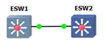
- Add a second EtherSwitch router to the project above and start the device.
- Add a link to connect the following.
- ESW1 FastEthernet1/1 <-> ESW2 FastEthernet1/1
- Set the following IP addresses and subnet masks.
- ESW1 VLAN 1: 192.168.1.1 255.255.255.0
- ESW2 VLAN 1: 192.168.1.2 255.255.255.0
- Open the console for both routers and practice using the following commands.
enableconfigure terminalusernameline vty 0 4login localexitinterface vlan 1ip addressno shutdownip default-gateway
- Verify the configuration using the following command on both routers.
show running-configpingshow arpshow mac-address-table
- Test the configuration using the following command to remotely manage one router from the other.
telnet
- Configure switch SSH access.
- Use the routers from above and practice using the following commands on both routers.
enableconfigure terminalhostnameip domain-namecrypto key generate rsaip ssh version 2line vty 0 4transport input ssh
- Verify the configuration using the following command on both routers.
show running-config
- Test the configuration using the following command to verify that telnet access is no longer supported.
telnet
- Test the configuration using the following command to remotely manage one router from the other.
ssh
- Save the configuration using the following command.
copy running-config startup-config
- Use the routers from above and practice using the following commands on both routers.


Lesson Summary
edit- A network switch is a computer networking device that connects devices together on a computer network, by using frame switching to receive, process and forward data to the destination device.[4]
- A network switch forwards data only to one or multiple devices that need to receive it, rather than broadcasting the same data out of each of its ports.[5]
- Switches forward frames through one of three methods: store and forward, cut through, and fragment free.[6]
- Store and forward buffers and verifies each frame before forwarding it.[7]
- Cut through starts forwarding after the frame's destination address is received.[8]
- Fragment free checks the first 64 bytes of the frame, to detect collision errors before forwarding occurs.[9]
- Some switches may support adaptive switching by automatically selecting between the three methods.[10]
- Switch global configuration is similar to router global configuration, including the
enable,disable,configure terminal,exit,hostname, andip domain-namecommands. - Switch password configuration is similar to router password configuration, including the
password,login,username,login local,exec-timeout,enable password,enable secret, andservice password-encryptioncommands. - Switch line configuration is similar to router line configuration, including the
show lineandlinecommands. - Switch interface configuration is similar to router interface configuration, including the
show ip interface,show ip interface brief,interface,ip address,shutdownandno shutdowncommands. - Switch SSH configuration is similar to router SSH configuration, including the
crypto key generate rsa,ip ssh version, andtransport inputcommands. - Switch configuration management is similar to router configuration management, including the
show running-config,show startup-config,copy,erase, andreloadcommands. - Switch remote management is similar to router remote management, including the
telnetandsshcommands. - Switch status is tested similar to router status, including the
pingandtraceroutecommands. - To enable remote management of a switch, assign an IP address to the management VLAN interface, which by default is VLAN 1.[11]
- To define a default gateway (router) when IP routing is disabled, use the
ip default-gatewaycommand in global configuration mode.[12] - To display the entries in the Address Resolution Protocol (ARP) table, use the
show ip arpcommand in user EXEC or privileged EXEC mode.[13] - Use the
show mac-address-tableprivileged EXEC command to display the MAC address table.[14]
Key Terms
edit- autonegotiation
- An Ethernet procedure by which two connected devices choose common transmission parameters, such as speed, duplex mode, and flow control.[15]
- flooding
- Sending incoming unknown-destination frames out on all ports.[16]
- Spanning Tree Protocol (STP)
- A network protocol that ensures a loop-free topology for Ethernet networks and allows a network design to include spare (redundant) links to provide automatic backup paths if an active link fails, without the danger of bridge loops, or the need for manual enabling or disabling of these backup links.[17]
Review Questions
edit-
A network switch is _____.A network switch is a computer networking device that connects devices together on a computer network, by using frame switching to receive, process and forward data to the destination device.
-
A network switch forwards data _____.A network switch forwards data only to one or multiple devices that need to receive it, rather than broadcasting the same data out of each of its ports.
-
Switches forward frames through one of three methods: _____, _____, and _____.Switches forward frames through one of three methods: store and forward, cut through, and fragment free.
-
Store and forward _____.Store and forward buffers and verifies each frame before forwarding it.
-
Cut through _____.Cut through starts forwarding after the frame's destination address is received.
-
Fragment free _____.Fragment free checks the first 64 bytes of the frame to detect collision errors before forwarding occurs.
-
Some switches may support adaptive switching by _____.Some switches may support adaptive switching by automatically selecting between the three forwarding methods.
-
Switch global configuration is similar to router global configuration, including the _____ commands.Switch global configuration is similar to router global configuration, including the enable, disable, configure terminal, exit, hostname, and ip domain-name commands.
-
Switch password configuration is similar to router password configuration, including the _____ commands.Switch password configuration is similar to router password configuration, including the password, login, username, login local, exec-timeout,enable password, enable secret, and service password-encryption commands.
-
Switch line configuration is similar to router line configuration, including the _____ commands.Switch line configuration is similar to router line configuration, including the show line and line commands.
-
Switch interface configuration is similar to router interface configuration, including the _____ commands.Switch interface configuration is similar to router interface configuration, including the show ip interface, show ip interface brief, interface,ip address, shutdown and no shutdown commands.
-
Switch SSH configuration is similar to router SSH configuration, including the _____ commands.Switch SSH configuration is similar to router SSH configuration, including the crypto key generate rsa, ip ssh version, and transport input commands.
-
Switch configuration management is similar to router configuration management, including the _____ commands.Switch configuration management is similar to router configuration management, including the show running-config, show startup-config, copy, erase, and reload commands.
-
Switch remote management is similar to router remote management, including the _____ commands.Switch remote management is similar to router remote management, including the telnet and ssh commands.
-
Switch status is tested similar to router status, including the _____ commands.Switch status is tested similar to router status, including the ping and traceroute commands.
-
To enable remote management of a switch, _____.To enable remote management of a switch, assign an IP address to the management VLAN interface, which by default is VLAN 1.
-
To define a default gateway (router) when IP routing is disabled, use _____.To define a default gateway (router) when IP routing is disabled, use the ip default-gateway command in global configuration mode.
-
To display the entries in the Address Resolution Protocol (ARP) table, use _____.To display the entries in the Address Resolution Protocol (ARP) table, use the show ip arp command in user EXEC or privileged EXEC mode.
-
Use the _____ command to display the MAC address table.Use the show mac-address-table privileged EXEC command to display the MAC address table.
Assessments
edit- Flashcards: Quizlet: CCENT - Switching
- Quiz: Quizlet: CCENT - Switching
See Also
editReferences
edit- ↑ Cisco: ICND1 Exam Topics
- ↑ Cisco: IP Addressing Services Command Reference
- ↑ Cisco: Cisco IOS LAN Switching Command Reference
- ↑ Wikipedia: Network switch
- ↑ Wikipedia: Network switch
- ↑ Wikipedia: Network switch
- ↑ Wikipedia: Network switch
- ↑ Wikipedia: Network switch
- ↑ Wikipedia: Network switch
- ↑ Wikipedia: Network switch
- ↑ TechRepublic: Five Things You Should Know About Configuring a Cisco IOS Switch
- ↑ Cisco: IP Addressing Services Command Reference
- ↑ Cisco: IP Addressing Services Command Reference
- ↑ Cisco: Cisco IOS LAN Switching Command Reference
- ↑ Wikipedia: Autonegotiation
- ↑ Wikipedia: MAC flooding
- ↑ Wikipedia: Spanning Tree Protocol
Lesson 11 - VLANs
editThis lesson covers VLANs and VLAN routing.
Objectives and Skills
editObjectives and skills for the VLANs portion of Cisco CCENT certification include:[1]
- Describe how VLANs create logically separate networks and the need for routing between them
- Explain network segmentation and basic traffic management concepts
- Configure and verify VLANs
- Configure and verify trunking on Cisco switches
- DTP (topic)
- Auto-negotiation
- Configure and verify interVLAN routing (router on a stick)
- Sub interfaces
- Upstream routing
- Encapsulation
- Configure SVI interfaces.
Readings
editMultimedia
edit- YouTube: VLANs - CompTIA Network+ N10-005: 1.4
- YouTube: Configuring VLANs - CompTIA Network+ N10-005: 2.1
- YouTube: VLAN Trunking Protocol - CompTIA Network+ N10-005: 2.1
- YouTube: CCNA And CCNP Tutorial: VLAN Trunking Protocol (VTP)
- YouTube: Cisco Inter-VLAN Routing on a Stick
- YouTube: Switched Virtual Interfaces for Inter-VLAN Routing
- YouTube: 802.1Q and Trunking
Examples
editSwitch Configuration
editvlan
editTo add a VLAN and enter config-VLAN submode on a switch, use the vlan command in global configuration mode.[2]
vlan {<vlan-id> | <vlan-range>}
vlan 2
name
editTo name a VLAN on a switch, use the name command in VLAN configuration mode.[3]
name sale
switchport mode
editTo set the interface type, use the switchport mode command in interface configuration mode.[4]
switchport mode < access | trunk >
switchport mode access
switchport mode trunk
switchport access vlan
editTo set the VLAN when the interface is in access mode, use the switchport access vlan command in interface configuration or template configuration mode.[5]
switchport access vlan <vlan-id>
switchport access vlan 2
switchport trunk
editTo set the trunk characteristics when the interface is in trunking mode, use the switchport trunk command in interface configuration mode.[6]
switchport trunk { native vlan <vlan-id> | allowed vlan <vlan-list> }
switchport trunk native vlan 10
switchport trunk allowed vlan 2-3, 10
show vlan
editTo display VLAN information on a switch, use the show vlan command in privileged EXEC mode.[7]
show vlan [brief | id <vlan-id> | name <name> [ifindex] | <ifindex>]
show vlan
show vlan brief
show vlan 2
show vlan sales
show interfaces switchport
editTo display the administrative and operational status of a switching (nonrouting) port, use the show interfaces switchport command in user EXEC or privileged EXEC mode.[8]
show interfaces switchport
Command Sequence
editA command sequence to configure a switch for VLAN switching might be similar to the following.
enable
configure terminal
vlan 2
name sales
vlan 3
name r&d
exit

interface vlan 1
ip address 192.168.1.10 255.255.255.0
no shutdown
ip default-gateway 192.168.1.1

interface fastethernet1/0
switchport trunk encapsulation dot1q
switchport mode trunk
interface range fastethernet1/1 - 2
switchport access vlan 2
interface range fastethernet1/3 - 4
switchport access vlan 3
exit
exit

show vlan brief
show interface trunk
show interfaces switchport
EtherSwitch Router Configuration
editvlan database
editTo enter VLAN configuration mode on a router with a switch module, use the vlan database command in privileged EXEC mode.[9]
vlan database
vlan (VLAN)
editTo configure a specific VLAN, use the vlan command in VLAN configuration mode.[10]
vlan <vlan-id> [name <vlan-name>]
vlan 2 name sales
show vlan-switch
editTo display VLAN information, use the show vlan-switch command in user EXEC or privileged EXEC mode.[11]
show vlan-switch [brief | id <vlan> | name <name>]
show vlan-switch
show vlan-switch brief
show interface trunk
editTo display the interface-trunk information, use the show interface trunk command in user EXEC or privileged EXEC mode.[12]
show interface [ interface <interface-number> ] trunk [ module <number> | vlan <vlan> ]
show interface trunk
Command Sequence
editA command sequence to configure an EtherSwitch router for VLAN switching might be similar to the following.
enable
vlan database
vlan 2 name sales
vlan 3 name r&d
exit

configure terminal
interface vlan 1
ip address 192.168.1.10 255.255.255.0
no shutdown
ip default-gateway 192.168.1.1

interface fastethernet1/0
switchport mode trunk
interface range fastethernet1/1 - 2
switchport access vlan 2
interface range fastethernet1/3 - 4
switchport access vlan 3
exit
exit

show vlan-switch brief
show interface trunk
Router Configuration
editencapsulation dot1q
editTo enable IEEE 802.1Q encapsulation of traffic on a specified subinterface in a VLAN, use the encapsulation dot1q command in interface range configuration mode or subinterface configuration mode.[13]
encapsulation dot1q <vlan-id> [native]
show vlans
editTo display VLAN subinterfaces, use the show vlans command in privileged EXEC mode.[14]
show vlan
Command Sequence
editA command sequence to configure a router for VLAN routing might be similar to the following.
enable
configure terminal

interface fastethernet0/0
ip address 192.168.1.1 255.255.255.0
no shutdown

interface fastethernet0/0.2
encapsulation dot1q 2
ip address 192.168.2.1 255.255.255.0

interface fastethernet0/0.3
encapsulation dot1q 3
ip address 192.168.3.1 255.255.255.0

exit
exit

show ip interface brief
show vlans
Switch Virtual Interface Configuration
editCommand Sequence
editA command sequence to configure switch virtual interface (SVI) VLAN routing might be similar to the following.
enable
configure terminal

ip routing

interface vlan 2
ip address 192.168.2.1 255.255.255.0
no shutdown

interface vlan 3
ip address 192.168.3.1 255.255.255.0
no shutdown

exit
exit

show ip route
Activities
edit- Configure and test switching.

- Add an EtherSwitch router and four VPCS PCs to a new GNS3 project and start the devices.
- Add links to connect the following.
- PC1 Ethernet0 <-> ESW1 FastEthernet1/1
- PC2 Ethernet0 <-> ESW1 FastEthernet1/2
- PC3 Ethernet0 <-> ESW1 FastEthernet1/3
- PC4 Ethernet0 <-> ESW1 FastEthernet1/4
- Set the following IP addresses and subnet masks.
- ESW1 VLAN1: 192.168.1.10 255.255.255.0
- PC1 Ethernet0: 192.168.1.11 255.255.255.0
- PC2 Ethernet0: 192.168.1.12 255.255.255.0
- PC3 Ethernet0: 192.168.1.13 255.255.255.0
- PC4 Ethernet0: 192.168.1.14 255.255.255.0
- Test the configuration using the following command on the switch and the PCs. Test all switch and PC addresses. All tests should be successful.
ping
- Configure and test VLAN switching.
- Using the project from above, create the following VLANs.
- VLAN 2: sales, FastEthernet1/1, FastEthernet1/2
- VLAN 3: r&d, FastEthernet1/3, FastEthernet1/4
- Open the console for the switch and practice using the following commands.
enablevlan databasevlanexitconfigure terminalinterfaceswitchport access
- Verify the configuration using the following commands.
show running-configshow vlan-switch
- Test the configuration using the following command on the switch and the PCs. Test all switch and PC addresses. Only connections on the same VLAN should be successful.
ping
- Using the project from above, create the following VLANs.
- Configure and test VLAN routing.

- Add a router to the project from above and start the device.
- Add a link to connect the following.
- R1 FastEthernet0/0 <-> ESW1 FastEthernet1/0
- Set the following IP addresses, subnet masks, and default gateways for the switch and PCs.
- R1 FastEthernet0/0: 192.168.1.1 255.255.255.0
- R1 FastEthernet0/0.2: 192.168.2.1 255.255.255.0
- R1 FastEthernet0/0.3: 192.168.3.1 255.255.255.0
- ESW1 VLAN1: 192.168.1.10 255.255.255.0 192.168.1.1
- PC1 Ethernet0: 192.168.2.11 255.255.255.0 192.168.2.1
- PC2 Ethernet0: 192.168.2.12 255.255.255.0 192.168.2.1
- PC3 Ethernet0: 192.168.3.13 255.255.255.0 192.168.3.1
- PC4 Ethernet0: 192.168.3.14 255.255.255.0 192.168.3.1
- Open the console for the router and practice using the following commands.
enableconfigure terminalinterfaceencapsulationip addressexit
- Verify the configuration using the following commands.
show ip interface briefshow vlans
- Open the console for the switch and practice using the following commands.
enableconfigure terminalinterfaceip addressip default-gatewayswitchport mode trunkexit
- Verify the configuration using the following commands.
show vlan-switchshow interface trunk
- Test the configuration using the following commands on the router, switch, and the PCs. Test all router, switch, and PC addresses. All tests should be successful.
pingtrace
- Configure and test switch virtual interface (SVI) routing.
- Remove the router from the project above.
- Set the following IP addresses and subnet masks for the switch.
- ESW1 VLAN2: 192.168.2.1 255.255.255.0
- ESW1 VLAN3: 192.168.3.1 255.255.255.0
- Open the console for the router and practice using the following commands.
enableconfigure terminalinterfaceip addressexitip routing
- Verify the configuration using the following commands.
show ip route
- Test the configuration using the following commands on the switch and the PCs. Test all switch and PC addresses. All tests should be successful.
pingtrace


Lesson Summary
edit- A virtual LAN (VLAN) is any broadcast domain that is partitioned and isolated in a computer network at the data link layer (OSI layer 2).[15]
- Managed switches can mark packets through tagging, so that a single interconnect (trunk) may be used to transport data for multiple VLANs.[16]
- VLANs allow network administrators to group hosts together even if the hosts are not on the same network switch.[17]
- VLAN Trunking Protocol (VTP) is a Cisco proprietary protocol that propagates the definition of Virtual Local Area Networks (VLAN) on the whole local area network.[18]
- IEEE 802.1Q is the networking standard that supports virtual LANs (VLANs) on an Ethernet network.[19]
- Under IEEE 802.1Q, the maximum number of VLANs on a given Ethernet network is 4,094.[20]
- A VLAN ID is added only if the frame is forwarded out a port configured as a trunk link. If the frame is to be forwarded out a port configured as an access link, the ISL encapsulation is removed.[21]
- Switch port mode settings available are:[22]
- Access - Puts the Ethernet port into permanent nontrunking mode.
- Trunk - Puts the Ethernet port into permanent trunking mode.
- Dynamic Auto - Makes the Ethernet port willing to convert the link to a trunk link. This is the default mode for all Ethernet ports.
- Dynamic Desirable - Makes the port actively attempt to convert the link to a trunk link.
- Nonegotiate - Disables DTP.
- Dynamic Trunking Protocol (DTP) is a proprietary networking protocol developed by Cisco Systems for the purpose of negotiating trunking on a link between two VLAN-aware switches, and for negotiating the type of trunking encapsulation to be used.[23]
- A "router on a stick", is a router that has a single physical or logical connection to a network, and is often used to forward traffic between locally attached hosts on separate logical routing domains or to facilitate routing table administration, distribution and relay.[24]
- A switched virtual interface (SVI) is a VLAN of switch ports represented by one interface to a routing or bridging system. An SVI cannot be activated unless associated with a physical port.[25]
- To add a VLAN and enter config-VLAN submode on a switch, use the
vlancommand in global configuration mode.[26] - To name a VLAN on a switch, use the
namecommand in VLAN configuration mode.[27] - To set the interface type, use the
switchport modecommand in interface configuration mode.[28] - To set the VLAN when the interface is in access mode, use the
switchport access vlancommand in interface configuration or template configuration mode.[29] - To set the trunk characteristics when the interface is in trunking mode, use the
switchport trunkcommand in interface configuration mode.[30] - To display VLAN information on a switch, use the
show vlancommand in privileged EXEC mode.[31] - To display the administrative and operational status of a switching (nonrouting) port, use the
show interfaces switchportcommand in user EXEC or privileged EXEC mode.[32]
Key Terms
edit- access interface
- A network link carrying a single VLAN, without VLAN tagging.[33]
- trunk interface
- A network link with VLAN tagging, able to carry multiple VLANs.[34]
- trunking administrative mode
- The configured port trunking setting.[35]
- trunking operational mode
- The current trunking behavior of a given port after negotiating with the neighboring port.[36]
Review Questions
edit-
A virtual LAN (VLAN) is _____.A virtual LAN (VLAN) is any broadcast domain that is partitioned and isolated in a computer network at the data link layer (OSI layer 2).
-
Managed switches can _____.Managed switches can mark packets through tagging, so that a single interconnect (trunk) may be used to transport data for multiple VLANs.
-
VLANs allow network administrators to _____.VLANs allow network administrators to group hosts together even if the hosts are not on the same network switch.
-
VLAN Trunking Protocol (VTP) is _____.VLAN Trunking Protocol (VTP) is a Cisco proprietary protocol that propagates the definition of Virtual Local Area Networks (VLAN) on the whole local area network.
-
IEEE 802.1Q is _____.IEEE 802.1Q is the networking standard that supports virtual LANs (VLANs) on an Ethernet network.
-
Under IEEE 802.1Q, the maximum number of VLANs on a given Ethernet network is _____.Under IEEE 802.1Q, the maximum number of VLANs on a given Ethernet network is 4,094.
-
A VLAN ID is added only if _____. If the frame is to be forwarded out a port configured as an access link, the _____.A VLAN ID is added only if the frame is forwarded out a port configured as a trunk link. If the frame is to be forwarded out a port configured as an access link, the ISL encapsulation is removed.
-
Switch port mode settings available are:Switch port mode settings available are:
Access - Puts the Ethernet port into permanent nontrunking mode.
Trunk - Puts the Ethernet port into permanent trunking mode.
Dynamic Auto - Makes the Ethernet port willing to convert the link to a trunk link. This is the default mode for all Ethernet ports.
Dynamic Desirable - Makes the port actively attempt to convert the link to a trunk link.
Nonegotiate - Disables DTP. -
Dynamic Trunking Protocol (DTP) is _____.Dynamic Trunking Protocol (DTP) is a proprietary networking protocol developed by Cisco Systems for the purpose of negotiating trunking on a link between two VLAN-aware switches, and for negotiating the type of trunking encapsulation to be used.
-
A "router on a stick", is _____.A "router on a stick", is a router that has a single physical or logical connection to a network, and is often used to forward traffic between locally attached hosts on separate logical routing domains or to facilitate routing table administration, distribution and relay.
-
A switched virtual interface (SVI) is _____.A switched virtual interface (SVI) is a VLAN of switch ports represented by one interface to a routing or bridging system. An SVI cannot be activated unless associated with a physical port.
-
To add a VLAN and enter config-VLAN submode on a switch, use the _____ command in global configuration mode.To add a VLAN and enter config-VLAN submode on a switch, use the vlan command in global configuration mode.
-
To name a VLAN on a switch, use the _____ command in VLAN configuration mode.To name a VLAN on a switch, use the name command in VLAN configuration mode.
-
To set the interface type, use the _____ command in interface configuration mode.To set the interface type, use the switchport mode command in interface configuration mode.
-
To set the VLAN when the interface is in access mode, use the _____ command in interface configuration or template configuration mode.To set the VLAN when the interface is in access mode, use the switchport access vlan command in interface configuration or template configuration mode.
-
To set the trunk characteristics when the interface is in trunking mode, use the _____ command in interface configuration mode.To set the trunk characteristics when the interface is in trunking mode, use the switchport trunk command in interface configuration mode.
-
To display VLAN information on a switch, use the _____ command in privileged EXEC mode.To display VLAN information on a switch, use the show vlan command in privileged EXEC mode.
-
To display the administrative and operational status of a switching (nonrouting) port, use the _____ command in user EXEC or privileged EXEC mode.To display the administrative and operational status of a switching (nonrouting) port, use the show interfaces switchport command in user EXEC or privileged EXEC mode.
Assessments
edit- Flashcards: Quizlet: CCENT - VLANS
- Quiz: Quizlet: CCENT - VLANS
See Also
editReferences
edit- ↑ Cisco: ICND1 Exam Topics
- ↑ Cisco: IOS LAN Switching Command Reference
- ↑ Cisco: IOS LAN Switching Command Reference
- ↑ Cisco: IOS Interface and Hardware Component Command Reference
- ↑ Cisco: IOS Interface and Hardware Component Command Reference
- ↑ Cisco: IOS Interface and Hardware Component Command Reference
- ↑ Cisco: IOS LAN Switching Command Reference
- ↑ Cisco: IOS Interfaces and Hardware Component Command Reference
- ↑ Cisco: IOS LAN Switching Command Reference
- ↑ Cisco: IOS LAN Switching Command Reference
- ↑ Cisco: IOS LAN Switching Command Reference
- ↑ Cisco: IOS LAN Switching Command Reference
- ↑ Cisco: IOS LAN Switching Command Reference
- ↑ Cisco: IOS LAN Switching Command Reference
- ↑ Wikipedia: Virtual LAN
- ↑ Wikipedia: Virtual LAN
- ↑ Wikipedia: Virtual LAN
- ↑ Wikipedia: VLAN Trunking Protocol
- ↑ Wikipedia: IEEE 802.1Q
- ↑ Wikipedia: Virtual LAN
- ↑ Wikipedia: Virtual LAN
- ↑ Wikipedia: Dynamic Trunking Protocol
- ↑ Wikipedia: Dynamic Trunking Protocol
- ↑ Wikipedia: Router on a stick
- ↑ Wikipedia: Switch virtual interface
- ↑ Cisco: IOS LAN Switching Command Reference
- ↑ Cisco: IOS LAN Switching Command Reference
- ↑ Cisco: IOS Interface and Hardware Component Command Reference
- ↑ Cisco: IOS Interface and Hardware Component Command Reference
- ↑ Cisco: IOS Interface and Hardware Component Command Reference
- ↑ Cisco: IOS LAN Switching Command Reference
- ↑ Cisco: IOS Interfaces and Hardware Component Command Reference
- ↑ Wikipedia: Virtual LAN
- ↑ Wikipedia: Virtual LAN
- ↑ Wikipedia: Dynamic Trunking Protocol
- ↑ Wikipedia: Dynamic Trunking Protocol
Lesson 12 - Security
editThis lesson covers security.
Objectives and Skills
editObjectives and skills for the security portion of Cisco CCENT certification include:[1]
- Configure and verify network device security features
- Device password security
- Enable secret vs. enable
- Transport
- Disable telnet
- SSH
- VTYs
- Physical security
- Service password
- Describe external authentication methods
- Configure and verify switch port security
- Sticky mac
- MAC address limitation
- Static/dynamic
- Violation modes
- Err disable
- Shutdown
- Protect restrict
- Shutdown unused ports
- Err disable recovery
- Assign unused ports in unused VLANs
- Putting Native VLAN to other than VLAN 1
Readings
editMultimedia
editExamples
editDevice Security
edit- Review Cisco Networking/CCENT/IOS Basics#Password Configuration
- Review Cisco Networking/CCENT/Remote Management#Line Configuration
- Review Cisco Networking/CCENT/Remote Management#Interface Configuration
- Review Cisco Networking/CCENT/Remote Management#SSH Configuration
Port Security Configuration
editNote: The following commands are not supported by NM-16ESW network modules. See Cisco: EtherSwitch Network Module 802.1x Authentication for an alternative. Port security is included in the Cisco CCENT exam, but 802.1x implementation is not.
switchport port-security
editTo enable port security on an interface, use the switchport port-security command in interface configuration mode.[2]
switchport port-security
switchport port-security mac-address
editTo add a MAC address to the list of secure MAC addresses, use the switchport port-security mac-address command in interface configuration mode.[3]
switchport port-security mac-address { <mac-addr> | sticky [<mac-addr>] [ vlan <vlan> [voice] | <vlan-list> ] }
switchport port-security mac-address 1a:6f:7c:8e:2h:3a
switchport port-security mac-address default
switchport port-security maximum
editTo set the maximum number of secure MAC addresses on a port, use the switchport port-security maximum command in interface configuration mode.[4]
switchport port-security maximum <maximum> [ vlan <vlan> | <vlan-list> ]
switchport port-security maximum 1
switchport port-security violation
editTo set the action to be taken when a security violation is detected, use the switchport port-security violation command in interface configuration mode.[5]
switchport port-security violation { shutdown | restrict | protect }
switchport port-security violation shutdown
switchport port-security violation restrict
switchport port-security violation protect
show port-security
editTo display port-security settings for an interface or for the switch, use the show port-security command in global configuration mode.[6]
show port-security [interface interface_id] [address]
show port-security
show port-security interface fastethernet 1/1
show port-security address
Command Sequence
editA command sequence to configure port security might be similar to the following.
enable
configure terminal

interface range fa1/0 - 15
switchport port-security mac-address sticky
switchport port-security maximum 1
switchport port-security violation restrict
exit
exit

show port-security
show port-security address
exit
Activities
edit- Configure and verify device security.
- Add a router, an EtherSwitch router, and four VPCS PCs to a new GNS3 project and start the devices.
- Add links to connect the following.
- R1 FastEthernet0/0 <-> ESW1 FastEthernet1/0
- PC1 Ethernet0 <-> ESW1 FastEthernet1/1
- PC2 Ethernet0 <-> ESW1 FastEthernet1/2
- PC3 Ethernet0 <-> ESW1 FastEthernet1/3
- PC4 Ethernet0 <-> ESW1 FastEthernet1/4
- Set the following IP addresses, subnet masks, and default gateways for the switch and PCs.
- R1 FastEthernet0/0: 192.168.1.1 255.255.255.0
- ESW1 VLAN1: 192.168.1.10 255.255.255.0 192.168.1.1
- PC1 Ethernet0: 192.168.1.11 255.255.255.0 192.168.1.1
- PC2 Ethernet0: 192.168.1.12 255.255.255.0 192.168.1.1
- PC3 Ethernet0: 192.168.1.13 255.255.255.0 192.168.1.1
- PC4 Ethernet0: 192.168.1.14 255.255.255.0 192.168.1.1
- Add username and password security to the console, aux, and vty lines, add a password to protect global configuration mode, and encrypt all passwords on both routers using the following commands.
enableconfigure terminalusernamelinelogin localenable secretservice password-encryption
- Allow only SSH connections to the vty lines of both routers using the following commands.
hostnameip domain-namecrypto key generate rsaip ssh version 2line vty 0 4transport input ssh
- Verify the configuration on both routers using the following command.
show running-config
- Exit the router console session and open the console again to test the configuration.
- Exit the router console session and open a console on the aux line to test the configuration.
- Test vty configuration using the following command to verify that telnet access is no longer supported.
telnet
- Test vty configuration using the following command to remotely manage one router from the other.
ssh
- Configure and verify switch port security. Note: EtherSwitch routers do not support the switchport port-security command. Use a Cisco switch, if available, or review CiscoSkills.net: Configuring Port Security.
- Add dynamic port security and limit connections to only 1 allowed device per port in restricted mode using the following commands.
switchport port-security mac-addressswitchport port-security maximumswitchport port-security violation
- Shutdown unused ports.
- Verify the configuration using the following commands.
show port-securityshow port-security address
- Test the configuration by pinging all four PCs. The test should be successful for all devices.
- Remove and add links to connect the following.
- PC3 Ethernet0 <-> ESW1 FastEthernet1/4
- PC4 Ethernet0 <-> ESW1 FastEthernet1/3
- Test the configuration by pinging all four PCs. The test should be successful for PC1 and PC2, and unsuccessful for PC3 and PC4.
- Verify the configuration using the following commands.
show port-securityshow port-security address
- Remove and add links to connect the following.
- PC3 Ethernet0 <-> ESW1 FastEthernet1/3
- PC4 Ethernet0 <-> ESW1 FastEthernet1/4
- Test the configuration by pinging all four PCs. The test should be successful for all devices.
- Add dynamic port security and limit connections to only 1 allowed device per port in restricted mode using the following commands.
- Configure VLAN security.
- Use the configuration from above. Change the native VLAN to VLAN 10, put existing devices in VLAN 10, and assign unused ports to VLAN 99 using the following commands on the EtherSwitch router.
enablevlan databasevlanexitconfigure terminalinterface rangeswitchport access
- Test the configuration by pinging all four PCs. The test should be successful for all devices.
- Remove and add links to connect the following.
- PC4 Ethernet0 <-> ESW1 FastEthernet1/5
- Test the configuration by pinging all four PCs. The test should be successful for PC1, PC2, and PC3, and unsuccessful for PC4.
- Configure the router to access the EtherSwitch router on VLAN 10 using the following commands.
enableconfigure terminalinterfaceencapsulationexit
- Test the configuration by pinging the switch from the router. The test should be successful.
- Use the configuration from above. Change the native VLAN to VLAN 10, put existing devices in VLAN 10, and assign unused ports to VLAN 99 using the following commands on the EtherSwitch router.
Lesson Summary
edit- Network security consists of the policies adopted to prevent and monitor authorized access, misuse, modification, or denial of a computer network and network-accessible resources.[7]
- Network security requires physical security, access control, authentication, and authorization.[8]
- Cisco IOS supports Authentication, Authorization, and Accounting (AAA) using either RADIUS or TACACS+ protocols.[9]
- MAC filtering is a security access control method whereby the 48-bit address assigned to each network card is used to determine access to the network.[10]
- MAC filtering can be circumvented by identifying a valid MAC through observation and then spoofing one's own MAC into a validated one.[11]
- MAC spoofing may done in the Windows Registry or by using command-line tools on a Linux platform.[12]
- Cisco Catalyst switches support MAC filtering on a port-by-port basis using port security.[13]
- Port security may be configured statically with a list, dynamically based on the first given number of addresses detected, or a combination of these two methods.[14]
- When port security is configured, the default settings are to allow only one MAC address per port, and to shut down the port if the allowed number of addresses is exceeded.[15]
- Rather than shutting down the port, the port security violation mode may be set to
restrictaccess and send an SNMP alert.[16] - Port security shutdown ports may also be set to recover automatically using the
errdisable recovery cause psecure-violationcommand in global configuration mode.[17] - The default erridsable recovery time is 300 seconds. This may be altered using the
errdisable recovery intervalcommand.[18] - Port security dynamic MAC addresses are not remembered by default. They may be added to the running configuration by enabling
stickymode.[19] - To enable port security on an interface, use the
switchport port-securitycommand in interface configuration mode.[20] - To add a MAC address to the list of secure MAC addresses, use the
switchport port-security mac-addresscommand in interface configuration mode.[21] - To set the maximum number of secure MAC addresses on a port, use the
switchport port-security maximumcommand in interface configuration mode.[22] - To set the action to be taken when a security violation is detected, use the
switchport port-security violationcommand in interface configuration mode.[23] - To display port-security settings for an interface or for the switch, use the
show port-securitycommand in global configuration mode.[24] - Additional switch security options include shutting down unused ports, assigning unused ports to unused VLANs, and setting the native VLAN to a VLAN other than 1.[25]
Key Terms
edit- AAA
- An acronym for authentication, authorization, and accounting, which generically refers to a protocol used for this purpose.[26]
- RADIUS (Remote Authentication Dial-In User Service)
- A networking protocol that provides centralized authentication, authorization, and accounting (AAA) management for users who connect and use a network service.[27]
- TACACS+ (Terminal Access Controller Access-Control System Plus
- A protocol developed by Cisco and released as an open standard that handles authentication, authorization, and accounting (AAA) services.[28]
Review Questions
edit-
Network security consists of _____.Network security consists of the policies adopted to prevent and monitor authorized access, misuse, modification, or denial of a computer network and network-accessible resources.
-
Network security requires _____.Network security requires physical security, access control, authentication, and authorization.
-
Cisco IOS supports Authentication, Authorization, and Accounting (AAA) using _____.Cisco IOS supports Authentication, Authorization, and Accounting (AAA) using either RADIUS or TACACS+ protocols.
-
MAC filtering is _____.MAC filtering is a security access control method whereby the 48-bit address assigned to each network card is used to determine access to the network.
-
MAC filtering can be circumvented by _____.MAC filtering can be circumvented by identifying a valid MAC through observation and then spoofing one's own MAC into a validated one.
-
MAC spoofing may done _____.MAC spoofing may done in the Windows Registry or by using command-line tools on a Linux platform.
-
Cisco Catalyst switches support MAC filtering on a port-by-port basis using _____.Cisco Catalyst switches support MAC filtering on a port-by-port basis using port security.
-
Port security may be configured _____.Port security may be configured statically with a list, dynamically based on the first given number of addresses detected, or a combination of these two methods.
-
When port security is configured, the default settings are _____.When port security is configured, the default settings are to allow only one MAC address per port, and to shut down the port if the allowed number of addresses is exceeded.
-
Rather than shutting down the port, the port security violation mode may be set to _____.Rather than shutting down the port, the port security violation mode may be set to restrict access and send an SNMP alert.
-
Port security shutdown ports may also be set to _____.Port security shutdown ports may also be set to recover automatically using the errdisable recovery cause psecure-violation command in global configuration mode.
-
The default errdisable recovery time is _____ seconds. This may be altered using the _____ command.The default errdisable recovery time is 300 seconds. This may be altered using the errdisable recovery interval command.
-
Dynamic addresses are not remembered by default. They may be added to the running configuration by enabling _____ mode.Dynamic addresses are not remembered by default. They may be added to the running configuration by enabling sticky mode.
-
To enable port security on an interface, use the _____ command in interface configuration mode.To enable port security on an interface, use the switchport port-security command in interface configuration mode.
-
To add a MAC address to the list of secure MAC addresses, use the _____ command in interface configuration mode.To add a MAC address to the list of secure MAC addresses, use the _____ command in interface configuration mode.
-
To set the maximum number of secure MAC addresses on a port, use the _____ command in interface configuration mode.To set the maximum number of secure MAC addresses on a port, use the switchport port-security maximum command in interface configuration mode.
-
To set the action to be taken when a security violation is detected, use the _____ command in interface configuration mode.To set the action to be taken when a security violation is detected, use the switchport port-security violation command in interface configuration mode.
-
To display port-security settings for an interface or for the switch, use the _____ command in global configuration mode.To display port-security settings for an interface or for the switch, use the show port-security command in global configuration mode.
-
Additional switch security options include _____, _____, and _____.Additional switch security options include shutting down unused ports, assigning unused ports to unused VLANs, and setting the native VLAN to a VLAN other than 1.
Assessments
edit- Flashcards: Quizlet: CCENT - Security
- Quiz: Quizlet: CCENT - Security
See Also
editReferences
edit- ↑ Cisco: ICND1 Exam Topics
- ↑ Cisco: IOS Interface and Hardware Component Command Reference
- ↑ Cisco: IOS Interface and Hardware Component Command Reference
- ↑ Cisco: IOS Interface and Hardware Component Command Reference
- ↑ Cisco: IOS Interface and Hardware Component Command Reference
- ↑ Cisco: Catalyst 4500 Series Switch Cisco IOS Software Configuration Guide
- ↑ Wikipedia: Network security
- ↑ Wikipedia: Access control
- ↑ Cisco: Configuring Basic AAA on an Access Server
- ↑ Wikipedia: MAC filtering
- ↑ Wikipedia: MAC filtering
- ↑ Wikipedia: MAC filtering
- ↑ Wikipedia: MAC filtering
- ↑ Wikipedia: MAC filtering
- ↑ Wikipedia: MAC filtering
- ↑ Cisco: Catalyst 4500 Series Switch Cisco IOS Software Configuration Guide
- ↑ Cisco: Catalyst 4500 Series Switch Cisco IOS Software Configuration Guide
- ↑ Cisco: Catalyst 4500 Series Switch Cisco IOS Software Configuration Guide
- ↑ Cisco: Catalyst 4500 Series Switch Cisco IOS Software Configuration Guide
- ↑ Cisco: IOS Interface and Hardware Component Command Reference
- ↑ Cisco: IOS Interface and Hardware Component Command Reference
- ↑ Cisco: IOS Interface and Hardware Component Command Reference
- ↑ Cisco: IOS Interface and Hardware Component Command Reference
- ↑ Cisco: Catalyst 4500 Series Switch Cisco IOS Software Configuration Guide
- ↑ Cisco: ICND1 Exam Topics
- ↑ Wikipedia: AAA protocol
- ↑ Wikipedia: RADIUS
- ↑ Wikipedia: TACACS
Lesson 13 - Access Control Lists
editThis lesson covers access control lists.
Objectives and Skills
editObjectives and skills for the access control lists portion of Cisco CCENT certification include:[1]
- Describe the types, features, and applications of ACLs
- Standard (editing and sequence numbers)
- Extended
- Named
- Numbered
- Log option
- Configure and verify ACLs in a network environment
- Named
- Numbered
- Log option
- Configure and verify ACLs to filter network traffic
- Configure and verify ACLs to limit telnet and SSH access to the router
Readings
editMultimedia
editExamples
editaccess-list (IP standard)
editTo define a standard IP access list, use the standard version of the access-list command in global configuration mode.[2]
access-list <access-list-number> {deny | permit} <source> [<source-wildcard>] [log]
access-list 1 deny 127.0.0.0 0.255.255.255 log
access-list 1 permit any
access-list (IP extended)
editTo define an extended IP access list, use the extended version of the access-list command in global configuration mode.[3]
access-list <access-list-number> [dynamic <dynamic-name> [timeout <minutes>]] {deny | permit} <protocol> <source> <source-wildcard> <destination> <destination-wildcard> [log | log-input]]
access-list 101 permit tcp host 192.168.1.2 host 192.168.1.1 eq telnet
access-list 101 deny tcp any any eq telnet log
access-list 101 permit ip any any
ip access-list
editTo define an IP access list by name, use the ip access-list command in global configuration mode.[4]
ip access-list {standard | extended} access-list-name

ip access-list standard block-private
deny 10.0.0.0 0.255.255.255 log

ip access-list extended filter-ssh
permit tcp host 192.168.1.2 host 192.168.1.1 eq 22
deny tcp any any eq 22 log
permit ip any any
ip access-group
editTo control access to an interface, use the ip access-group command in interface configuration mode.[5]
ip access-group {<access-list-number> | <access-list-name>}{in | out}
ip access-group 1 out
ip access-group block-private out
ip access-group 101 in
ip access-group filter-ssh in
show access-lists
editTo display the contents of current access lists, use the show access-lists privileged EXEC command.[6]
show access-lists [<access-list-number> | <access-list-name>]
show access-lists
show access-lists 1
show access-lists block-private
show ip access-lists
editTo display the contents of all current IP access lists, use the show ip access-list EXEC command.[7]
show ip access-lists [access-list-number | access-list-name]
show ip access-lists 1
show ip access-lists block-private
Command Sequence
editA command sequence to configure port security might be similar to the following.
enable
configure terminal

access-list 1 deny 10.0.0.0 0.255.255.255 log
access-list 1 deny 172.16.0.0 0.15.255.255 log
access-list 1 deny 192.168.0.0 0.0.255.255 log
access-list 1 permit any

access-list 101 permit tcp host 192.168.1.2 host 192.168.1.1 eq 22
access-list 101 deny tcp any any eq 22 log
access-list 101 permit ip any any

interface fastethernet 0/0
ip access-group 101 in

interface fastethernet 0/1
ip access-group 1 out

exit
exit

show access-lists
show ip interface
exit
Activities
edit- Complete the Cisco Access Lists training tutorial.
- Configure numbered standard ACLs to filter network traffic.
- Add three routers and two VPCS PCs to a new GNS3 project.
- Add links to connect the following.
- PC1 Ethernet0 <-> R1 FastEthernet0/0
- R1 FastEthernet0/1 <-> R2 FastEthernet0/0
- R2 FastEthernet0/1 <-> R3 FastEthernet0/0
- PC2 Ethernet0 <-> R3 FastEthernet0/1
- Start the devices.
- Set the following IP addresses, subnet masks, and for the PCs, default gateways
- R1 FastEthernet0/0 = 192.168.1.1 255.255.255.0
- R1 FastEthernet0/1 = 192.168.2.1 255.255.255.0
- R2 FastEthernet0/0 = 192.168.2.2 255.255.255.0
- R2 FastEthernet0/1 = 192.168.3.1 255.255.255.0
- R3 FastEthernet0/0 = 192.168.3.2 255.255.255.0
- R3 FastEthernet0/1 = 192.168.4.1 255.255.255.0
- PC1 Ethernet0 = 192.168.1.11 255.255.255.0 192.168.1.1
- PC2 Ethernet0 = 192.168.4.11 255.255.255.0 192.168.4.1
- Add static routes or dynamic OSPF routing to connect all devices.
- Display the routing tables using the following command.
show ip route
- Test the configuration using the following commands from the routers and the PCs. Test all router and PC addresses. All tests should be successful.
pingtrace
- Add a numbered standard ACL to filter network traffic and prevent hosts on the different subnets from connecting to hosts on other subnets. Practice using the following commands.
access-listip access-groupshow access-listsshow ip interface
- Test the configuration using the following commands from the routers and the PCs. Test all router and PC addresses. All PC-to-router and router-to-router tests should be successful. The PC-to-PC test should fail.
pingtrace
- Configure numbered extended ACLs to filter network traffic.
- Remove all ACLs from the configuration above. Verify the configuration using the following command.
show access-lists
- Test the configuration using the following commands from the routers and the PCs. Test all router and PC addresses. All tests should be successful.
pingtrace
- Add a numbered extended ACL that permits ICMP connections to routers, but prevents ICMP connections to other network hosts. Allow all other IP traffic. Practice using the following commands.
access-listip access-groupshow access-listsshow ip interface
- Test the configuration using the following commands from the routers and the PCs. Test all router and PC addresses. All PC-to-router and router-to-router tests should be successful. The PC-to-PC test should fail.
pingtrace
- Remove all ACLs from the configuration above. Verify the configuration using the following command.
- Configure named standard ACLs to filter network traffic.
- Remove all ACLs from the configuration above. Verify the configuration using the following command.
show access-lists
- Test the configuration using the following commands from the routers and the PCs. Test all router and PC addresses. All tests should be successful.
pingtrace
- Add a named standard ACL to filter network traffic and prevent hosts on the different subnets from connecting to hosts on other subnets. Practice using the following commands.
access-listip access-groupshow ip access-listsshow ip interface
- Test the configuration using the following commands from the routers and the PCs. Test all router and PC addresses. All PC-to-router and router-to-router tests should be successful. The PC-to-PC test should fail.
pingtrace
- Remove all ACLs from the configuration above. Verify the configuration using the following command.
- Configure named extended ACLs to filter network traffic.
- Remove all ACLs from the configuration above. Verify the configuration using the following command.
show access-lists
- Test the configuration using the following commands from the routers and the PCs. Test all router and PC addresses. All tests should be successful.
pingtrace
- Add a named extended ACL that permits ICMP connections to routers, but prevents ICMP connections to other network hosts. Allow all other IP traffic. Practice using the following commands.
access-listip access-groupshow ip access-listsshow ip interface
- Test the configuration using the following commands from the routers and the PCs. Test all router and PC addresses. All PC-to-router and router-to-router tests should be successful. The PC-to-PC test should fail.
pingtrace
- Remove all ACLs from the configuration above. Verify the configuration using the following command.
- Configure ACLs to limit telnet and SSH access to the router.
- Remove all ACLs from the configuration above. Verify the configuration using the following command.
show access-lists
- Test the configuration using the following commands from the routers and the PCs. Test all router and PC addresses. All tests should be successful.
pingtrace
- Configure R2 to accept vty connections. Test the configuration using the following command from both routers. Both connections should be successful.
telnet
- Add an extended ACL that permits Telnet and SSH connections from R1 to R2, but prevents any other Telnet or SSH connections. Allow all other IP traffic. Practice using the following commands.
access-listip access-groupshow ip access-listsshow ip interface
- Test the configuration using the following commands from both routers. The connection from R1 to R2 should be successful. The connection from R3 to R2 should fail.
telnet
- Test the configuration using the following commands from the routers and the PCs. Test all router and PC addresses. All tests should be successful.
pingtrace
- Remove all ACLs from the configuration above. Verify the configuration using the following command.
Lesson Summary
edit- An access control list refers to rules that are applied to port numbers or IP addresses that are available on a host, each with a list of hosts and/or networks permitted to use the service.[8]
- Access control lists can generally be configured to control both inbound and outbound traffic, and in this context they are similar to firewalls.[9]
- To define a standard IP access list, use the standard version of the
access-listcommand in global configuration mode.[10] - Access lists may be configured to specifically
permitordenynetwork traffic.[11] - Access lists end with an implicit deny all. Only traffic explicitly permitted by the access list will be allowed.[12]
- Standard access lists filter based on source IP address.[13]
- Standard numbered access lists are numbered from 1 to 99 or from 1300 to 1999.[14]
- Access list wildcard masks are applied to IP addresses similar to the way subnet masks are applied, but with an opposite design. Subnet masks use 1-bits to identify the network. Access list wildcard masks use 1-bits to identify the host addresses to be filtered.[15]
- To define an extended IP access list, use the extended version of the
access-listcommand in global configuration mode.[16] - Extended access lists filter based on source and destination IP addresses, protocols, and port numbers.[17]
- Extended numbered access lists are numbered from 100 to 199 or from 2000 to 2699.[18]
- The
logaccess-list command option causes an informational logging message about the packet that matches the entry to be sent to the console.[19] - To define an IP access list by name, use the
ip access-listcommand in global configuration mode.[20] - To control access to an interface, use the
ip access-groupcommand in interface configuration mode.[21] - Access lists filter either inbound or outbound traffic based on the
ip access-groupoptions ofinorout.[22] - To display the contents of current access lists, use the
show access-listsprivileged EXEC command.[23] - To display the contents of all current IP access lists, use the
show ip access-listEXEC command.[24]
Key Terms
editIncluded in Lesson Summary
Review Questions
edit-
An access control list refers to _____.An access control list refers to rules that are applied to port numbers or IP addresses that are available on a host, each with a list of hosts and/or networks permitted to use the service.
-
Access control lists can generally be configured to _____, and in this context they are similar to _____.Access control lists can generally be configured to control both inbound and outbound traffic, and in this context they are similar to firewalls.
-
To define a standard IP access list, use _____.To define a standard IP access list, use the standard version of the access-list command in global configuration mode.
-
Access lists may be configured to specifically _____ or _____ network traffic.Access lists may be configured to specifically permit or deny network traffic.
-
Access lists end with _____. Only traffic _____ will be allowed.Access lists end with an implicit deny all. Only traffic explicitly permitted by the access list will be allowed.
-
Standard access lists filter based on _____.Standard access lists filter based on source IP address.
-
Standard numbered access lists are numbered _____ or _____.Standard numbered access lists are numbered from 1 to 99 or from 1300 to 1999.
-
Access list wildcard masks are applied to IP addresses similar to the way subnet masks are applied, but _____. Subnet masks use 1-bits to identify _____. Access list wildcard masks use 1-bits to identify _____.Access list wildcard masks are applied to IP addresses similar to the way subnet masks are applied, but with an opposite design. Subnet masks use 1-bits to identify the network. Access list wildcard masks use 1-bits to identify the host addresses to be filtered.
-
To define an extended IP access list, use _____.To define an extended IP access list, use the extended version of the access-list command in global configuration mode.
-
Extended access lists filter based on _____.Extended access lists filter based on source and destination IP addresses, protocols, and port numbers.
-
Extended numbered access lists are numbered _____ or _____.Extended numbered access lists are numbered from 100 to 199 or from 2000 to 2699.
-
The log access-list command option causes _____.The log access-list command option causes an informational logging message about the packet that matches the entry to be sent to the console.
-
To define an IP access list by name, use _____.To define an IP access list by name, use the ip access-list command in global configuration mode.
-
To control access to an interface, use _____.To control access to an interface, use the ip access-group command in interface configuration mode.
-
Access lists filter either inbound or outbound traffic based on _____.Access lists filter either inbound or outbound traffic based on the ip access-group options of in or out.
-
To display the contents of current access lists, use _____.To display the contents of current access lists, use the show access-lists privileged EXEC command.
-
To display the contents of all current IP access lists, use _____.To display the contents of all current IP access lists, use the show ip access-list EXEC command.
Assessments
edit- Flashcards: Quizlet: CCENT - Access Control Lists
- Quiz: Quizlet: CCENT - Access Control Lists
See Also
editReferences
edit- ↑ Cisco: ICND1 Exam Topics
- ↑ Cisco: IOS IP Command Reference
- ↑ Cisco: IOS IP Command Reference
- ↑ Cisco: Cisco IOS IP Command Reference
- ↑ Cisco: IOS IP Command Reference
- ↑ Cisco: IOS IP Command Reference
- ↑ Cisco: IOS IP Command Reference
- ↑ Wikipedia: Access control list
- ↑ Wikipedia: Access control list
- ↑ Cisco: IOS IP Command Reference
- ↑ Cisco: IOS IP Command Reference
- ↑ Cisco: IOS IP Command Reference
- ↑ Cisco: IOS IP Command Reference
- ↑ Cisco: IOS IP Command Reference
- ↑ Cisco: IOS IP Command Reference
- ↑ Cisco: IOS IP Command Reference
- ↑ Cisco: IOS IP Command Reference
- ↑ Cisco: IOS IP Command Reference
- ↑ Cisco: IOS IP Command Reference
- ↑ Cisco: Cisco IOS IP Command Reference
- ↑ Cisco: IOS IP Command Reference
- ↑ Cisco: IOS IP Command Reference
- ↑ Cisco: IOS IP Command Reference
- ↑ Cisco: IOS IP Command Reference
Lesson 14 - Troubleshooting
editThis lesson covers troubleshooting.
Objectives and Skills
editObjectives and skills for the troubleshooting portion of Cisco CCENT certification include:[1]
- Troubleshoot and correct common problems associated with IP addressing and host configurations
- Troubleshoot and resolve VLAN problems
- Identify that VLANs are configured
- Verify port membership is correct
- Correct IP address is configured
- Troubleshoot and resolve trunking problems on Cisco switches
- Verify correct trunk states
- Verify correct encapsulation is configured
- Correct VLANs are allowed
- Troubleshoot and resolve ACL issues
- Verify statistics
- Verify permitted networks
- Verify direction
- Interface
- Troubleshoot and resolve Layer 1 problems
- Framing
- CRC
- Runts
- Giants
- Dropped Packets
- Late Collisions
- Input/Output errors
Readings
editMultimedia
edit- YouTube: The Network Troubleshooting Process - CompTIA Network+ N10-005: 1.8
- YouTube: Switch and Routing Diagnostics - CompTIA Network+ N10-005: 2.1
- YouTube: Troubleshooting Switch Loops - CompTIA Network+ N10-005: 2.5
- YouTube: Troubleshooting Network Cabling - CompTIA Network+ N10-005: 2.5
- YouTube: Troubleshooting Port Configuration - CompTIA Network+ N10-005: 2.5
- YouTube: Troubleshooting VLAN Assignments - CompTIA Network+ N10-005: 2.5
- YouTube: Troubleshooting Bad Fiber Modules - CompTIA Network+ N10-005: 2.5
- YouTube: Troubleshooting Mismatched MTUs - CompTIA Network+ N10-005: 2.5
- YouTube: Troubleshooting Power Failures - CompTIA Network+ N10-005: 2.5
- YouTube: Troubleshooting Routing - CompTIA Network+ N10-005: 2.5
- YouTube: Troubleshooting Subnet Masks and Gateways - CompTIA Network+ N10-005: 2.5
- YouTube: Troubleshooting Duplicate IP Addresses - CompTIA Network+ N10-005: 2.5
- YouTube: Troubleshooting DNS - CompTIA Network+ N10-005: 2.5
- YouTube: Cisco Troubleshooting Exercise
Examples
editIP Addressing
editshow interfaces
editTo display statistics for all interfaces configured on the router or access server, use the show interfaces command in privileged EXEC mode.[2]
show interfaces
Review
edit- Review Cisco Networking/CCENT/Remote Management#show ip interface
- Review Cisco Networking/CCENT/Remote Management#show ip interface brief
- Review Cisco Networking/CCENT/Static Routing#show ip route
- Review Cisco Networking/CCENT/Switching#show arp
- Review Cisco Networking/CCENT/IOS Basics#show running-config
- Review Cisco Networking/CCENT/IOS Basics#show startup-config
- Review Cisco Networking/CCENT/Remote Management#ping
- Review Cisco Networking/CCENT/Static_Routing#trace / traceroute
- Review Cisco Networking/CCENT/Remote Management#telnet
VLANs
edit- Review Cisco Networking/CCENT/VLANs#show vlan
- Review Cisco Networking/CCENT/VLANs#show interface trunk
- Review Cisco Networking/CCENT/VLANs#show interfaces switchport
Access Control Lists
edit- Review Cisco Networking/CCENT/Access Control Lists#show access-lists
- Review Cisco Networking/CCENT/Access Control Lists#show ip access-lists
- Review Cisco Networking/CCENT/Remote Management#show ip interface
Layer 1 Problems
editActivities
edit- Troubleshoot and correct common problems associated with IP addressing and host configurations.
- Add two routers to a new GNS3 project and start the devices.
- Set the router global, password, interface, line, and remote management configurations to various matching and mismatched configurations.
- Practice verifying and troubleshooting the configurations using the following commands.
show interfacesshow ip interfaceshow ip interface briefshow ip routeshow arpshow running-configshow startup-configpingtrace / traceroutetelnetssh
- Troubleshoot and resolve VLAN and trunking problems.
- Add a router, an EtherSwitch router and four VPCS PCs to a new GNS3 project and start the devices.
- Set the VLANs, port membership, encapsulation, trunking, and IP addressing to various matching and mismatched configurations.
- Practice verifying and troubleshooting the configurations using the following commands.
show vlanshow interface trunkshow interfaces switchport
- Troubleshoot and resolve ACL issues.
- Add three routers and two VPCS PCs to a new GNS3 project and start the devices.
- Configure IP addressing and static or dynamic routing to connect all devices.
- Test the configuration using the following commands from the routers and the PCs. Test all router and PC addresses. All tests should be successful.
pingtrace
- Configure standard and extended ACLs to various matching and mismatched configurations.
- Practice verifying and troubleshooting the configurations using the following commands.
show access-listsshow ip access-listsshow ip interface
- Troubleshoot and resolve Layer 1 problems.
- Add two routers to a new GNS3 project and start the devices.
- Set the link between the devices to various matching and mismatched configurations.
- Practice verifying and troubleshooting Layer 1 problems using the following commands.
shutdownno shutdownshow interfacesshow cdp neighbors

Lesson Summary
edit- Troubleshooting is a logical, systematic search for the source of a problem so that it can be solved, and so the product or process can be made operational again.[3]
- Troubleshooting requires identification of the malfunction(s) or symptoms within a system. Then, experience is commonly used to generate possible causes of the symptoms. Determining the most likely cause is a process of elimination - eliminating potential causes of a problem. Finally, troubleshooting requires confirmation that the solution restores the product or process to its working state.[4]
- A basic principle in troubleshooting is to start from the simplest and most probable possible problems first.[5]
- Serial substitution involves checking each component in a system one by one, substituting known good components for each potentially suspect one.[6]
- Bisection involves separating a larger system into two or more subsystems to isolate and identify problems and causes.[7]
- One of the core principles of troubleshooting is that reproducible problems can be reliably isolated and resolved.[8]
- Intermittent problems are often the result of components that are thermally sensitive, because the resistance of a circuit varies with the temperature of the conductors in it.[9]
- Troubleshooters must always consider the possibility that there is more than one fault causing a given system failure.[10]
- Troubleshoot common problems associated with IP addressing and host configurations using the
show interfaces,show ip interface,show ip interface brief,show ip route,show arp,show running-config,show startup-config,ping,trace / traceroute,telnet, andsshcommands. - Troubleshoot VLAN and trunking problems using the
show vlan,show interface trunk, andshow interfaces switchportcommands. - Troubleshoot ACL issues using the
show access-lists,show ip access-lists, andshow ip interfacecommands. - Troubleshoot Layer 1 problems using the
show interfacesandshow cdp neighborscommands.
Key Terms
edit- CRC (cyclic redundancy check)
- An error-detecting code commonly used in digital networks and storage devices to detect accidental changes to raw data.[11]
- duplex mismatch
- A condition where two connected devices operate in different duplex modes, that is, one operates in half duplex while the other one operates in full duplex.[12]
- error disabled (err-disabled)
- A error situation detected on a port, resulting in the software shutting down that port.[13]
- giant
- An Ethernet frame that is longer than the IEEE standard 1,518 bytes.[14]
- late collision
- A collision that occurs more than 64 octets into the frame.[15]
- runt
- An Ethernet frame that is less than the IEEE 802.3's minimum length of 64 octets.[16]
- up and up
- Refers to the two interface states of line status and protocol status both being enabled.[17]
Review Questions
edit-
Troubleshooting is _____.Troubleshooting is a logical, systematic search for the source of a problem so that it can be solved, and so the product or process can be made operational again.
-
Troubleshooting requires _____.Troubleshooting requires identification of the malfunction(s) or symptoms within a system. Then, experience is commonly used to generate possible causes of the symptoms. Determining the most likely cause is a process of elimination - eliminating potential causes of a problem. Finally, troubleshooting requires confirmation that the solution restores the product or process to its working state.
-
A basic principle in troubleshooting is to _____.A basic principle in troubleshooting is to start from the simplest and most probable possible problems first.
-
Serial substitution involves _____.Serial substitution involves checking each component in a system one by one, substituting known good components for each potentially suspect one.
-
Bisection involves _____.Bisection involves separating a larger system into two or more subsystems to isolate and identify problems and causes.
-
One of the core principles of troubleshooting is that _____.One of the core principles of troubleshooting is that reproducible problems can be reliably isolated and resolved.
-
Intermittent problems are often the result of _____.Intermittent problems are often the result of components that are thermally sensitive, because the resistance of a circuit varies with the temperature of the conductors in it.
-
Troubleshooters must always consider the possibility that _____.Troubleshooters must always consider the possibility that there is more than one fault causing a given system failure.
-
Troubleshoot common problems associated with IP addressing and host configurations using the _____ commands.Troubleshoot common problems associated with IP addressing and host configurations using the show interfaces, show ip interface, show ip interface brief, show ip route, show arp, show running-config, show startup-config, ping, trace / traceroute, telnet, andssh commands.
-
Troubleshoot VLAN and trunking problems using the _____ commands.Troubleshoot VLAN and trunking problems using the show vlan, show interface trunk, and show interfaces switchport commands.
-
Troubleshoot ACL issues using the _____ commands.Troubleshoot ACL issues using the show access-lists, show ip access-lists, and show ip interface commands.
-
Troubleshoot Layer 1 problems using the _____ commands.Troubleshoot Layer 1 problems using the show interfaces and show cdp neighbors commands.
Assessments
edit- Flashcards: Quizlet: CCENT - Troubleshooting
- Quiz: Quizlet: CCENT - Troubleshooting
See Also
editReferences
edit- ↑ Cisco: ICND1 Exam Topics
- ↑ Cisco: IOS Interface Command Reference
- ↑ Wikipedia: Troubleshooting
- ↑ Wikipedia: Troubleshooting
- ↑ Wikipedia: Troubleshooting
- ↑ Wikipedia: Troubleshooting
- ↑ Wikipedia: Troubleshooting
- ↑ Wikipedia: Troubleshooting
- ↑ Wikipedia: Troubleshooting
- ↑ Wikipedia: Troubleshooting
- ↑ Wikipedia: Cyclic redundancy check
- ↑ Wikipedia: Duplex mismatch
- ↑ Cisco: Errdisable Port State Recovery on the Cisco IOS Platforms
- ↑ Wikipedia: Jumbo frame
- ↑ Wikipedia: Carrier sense multiple access with collision detection
- ↑ Wikipedia: Ethernet frame
- ↑ Odom, W. (2013). CCENT/CCNA ICND1 100-101 Official Cert Guide. Cisco. ISBN 9781587143854