Bridge Project Super Group
ENES-100 Super Group Bridge Project
editGroup Members
edit
Goal
editOur Goal is to research, design, and build a bridge that can weigh as little as possible while being able to hold as much as possible. We will learn how to design the bridge with the CAD software and possibly try to print it on the 3d printer.
Initial Research
editTypes of Bridges:
- Arch Bridge: An arch bridge is a bridge with abutments at each end shaped as a curved arch. Arch bridges work by transferring the weight of the bridge and its loads partially into a horizontal thrust restrained by the abutments at either side. A viaduct (a long bridge) may be made from a series of arches, although other more economical structures are typically used today.
- Through Arch Bridge: A through arch bridge, also known as a half-through arch bridge and through-type arch bridge, is a bridge made from materials such as steel or reinforced concrete in which the base of an arch structure is below the deck, but the top rises above it, so the deck passes through the arch. Cables or beams in tension suspend the central part of the deck from the arch.
- Beam Bridge: Beam bridges are the simplest structural forms for bridge spans supported by an abutment or pier at each end. No moments are transferred throughout the support, hence their structural type is known as simply supported.
- Tied-Arch Bridge: A tied-arch bridge is an arch bridge in which the outward-directed horizontal forces of the arch, or top chord, are borne as tension by the bottom chord (either tie-rods or the deck itself), rather than by the ground or the bridge foundations.Thrusts downward on such a bridge's deck are translated, as tension, by vertical ties of the deck to the curved top chord, tending to flatten it and thereby to push its tips outward into the abutments, like other arch bridges. However, in a tied-arch or bowstring bridge, these movements are restrained not by the abutments but by the bottom chord, which ties these tips together, taking the thrusts as tension, rather like the string of a bow that is being flattened. Therefore, the design is often called a bowstring-arch or bowstring-girder bridge
- Cantilever Bridge: A cantilever bridge is a bridge built using cantilevers, structures that project horizontally into space, supported on only one end. For small footbridges, the cantilevers may be simple beams; however, large cantilever bridges designed to handle road or rail traffic use trusses built from structural steel, or box girders built from prestressed concrete. The steel truss cantilever bridge was a major engineering breakthrough when first put into practice, as it can span distances of over 1,500 feet (460 m), and can be more easily constructed at difficult crossings by virtue of using little or no falsework.
- Girder Bridge: A girder bridge, in general, is a bridge built of girders placed on bridge abutments and foundation piers.[1] In turn, a bridge deck is built on top of the girders in order to carry traffic. A girder bridge is very likely the most commonly built and utilized bridge in the world. Its basic design can be compared to a log ranging from one side to the other across a river or creek when at its most simplified form. In modern girder steel bridges, the two most common girders are I-beam girders and box-girders. A girder bridge only requires a rigid horizontal structure, also known as a beam, and two supports at each end to rest upon it. These components are what allows the downward weight of the bridge and any traffic to travel across it.
- Segmental Bridge: A segmental bridge is a bridge built in short sections (called segments), i.e., one piece at a time, as opposed to traditional methods that build a bridge in very large sections. The bridge is made of concrete that is either cast-in-place (constructed fully in its final location) or precast concrete (built at another location and then transported to their final location for placement in the full structure).
- Suspension Bridge: A self-anchored suspension bridge is a suspension bridge in which the main cables attach to the ends of the deck, rather than to the ground via large anchorages. The design is well-suited for construction atop elevated piers, or in areas of unstable soils where anchorages would be difficult to construct.
- Trestle Bridge: A trestle (sometimes tressel) is a rigid frame used as a support, especially referring to a bridge composed of a number of short spans supported by such frames. In the context of trestle bridges, each supporting frame is generally referred to as a bent. Timber and iron trestles were extensively used in the 19th century, the former making up from 1 to 3% of the total length of the average railroad.[1] In the 21st century, steel and sometimes concrete trestles are commonly used to bridge particularly deep valleys while timber trestles remain common in certain areas.
- Truss Bridge: A truss bridge is a bridge whose load-bearing superstructure is composed of a truss, a structure of connected elements forming triangular units. The connected elements (typically straight) may be stressed from tension, compression, or sometimes both in response to dynamic loads. Truss bridges are one of the oldest types of modern bridges. The basic types of truss bridges shown in this article have simple designs which could be easily analyzed by 19th- and early 20th-century engineers. A truss bridge is economical to construct because it uses materials efficiently.
(This information was acquired by searching around wikipedia and other internet resources.)
Famous Bridges Throughout the World:
- Tower Bridge (London): Contains two towers with a runway. http://cdn3.list25.com/wp-content/uploads/2013/02/2.-Tower-Bridge.jpg
- Golden Gate Bridge (San Francisco): The iconic bridge in North America. It spans 2.7 kilometers. http://cdn3.list25.com/wp-content/uploads/2013/02/3.-Golden-Gate-Bridge.jpg
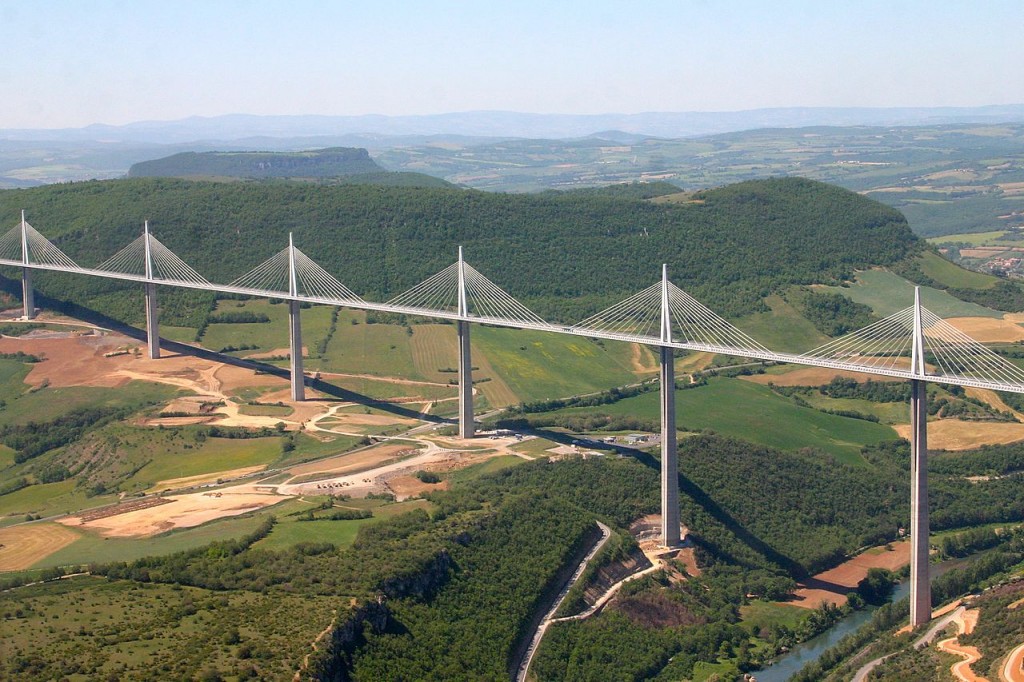
- Milau Bridge (France): 2.5 kilometers long, 343 meters off the ground. http://10mosttoday.com/wp-content/uploads/2013/09/ViaducdeMillau_france-1024x682.jpg
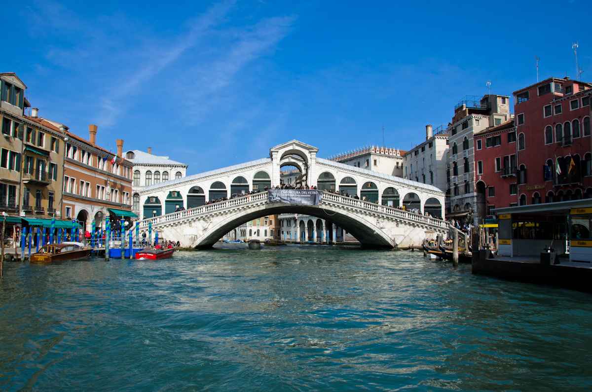
- Rilato Bridge (Venice, Italy): Built with Stone Arch Architecture, regarded as one of the most iconic bridges in all of Europe. http://upload.wikimedia.org/wikipedia/commons/8/83/Rialto_bridge_2011.jpg
- Si-o-se Pol (Iran): Regarded as one of the most famous bridges in the middle east, includes 33 arches.http://www.tishineh.com/tour/Pictures/Item/810/6309.jpg
- Stari Most (Bosnia and Herzegovina): Stood for 427 years, was restored in 2004. http://upload.wikimedia.org/wikipedia/commons/a/a2/Stari_Most22.jpg
- Sydney Harbor Bridge (Australia): Huge tourist site, regarded as one of the most recognizable architectural symbols in Australia. http://upload.wikimedia.org/wikipedia/commons/a/a8/Sydney_harbour_bridge_new_south_wales.jpg
Information and pictures found at : http://www.historyofbridges.com/famous-bridges/list-of-famous-bridges/
Interesting Bridges:
- The Moses Bridge (Netherlands) http://www.mentalfloss.com/blogs/wp-content/uploads/2012/04/mosesbridge3-565x423.jpg
- Da Vinci Bridge (Norway) http://www.mentalfloss.com/blogs/wp-content/uploads/2012/04/da-vinci-bridge-565x403.jpg
- Pythonburg BridgE (Amsterdam) http://www.mentalfloss.com/blogs/wp-content/uploads/2012/04/Ams112-565x362.jpg
- Rolling BridgE (London, England) http://www.mentalfloss.com/blogs/wp-content/uploads/2012/04/rollingbridge-565x423.jpg
- Ponte Vecchio Bridge (Florence, Italy) http://10mosttoday.com/wp-content/uploads/2013/09/Ponte_Vecchio_florence.jpg
- Millau Villaduct (Milau, France) http://10mosttoday.com/wp-content/uploads/2013/09/ViaducdeMillau_france-1024x682.jpg
- Helix Bridge (Singapore, Japan) http://cdn4.list25.com/wp-content/uploads/2013/02/25.-Helix-Bridge.jpg
- Henderson Waves Bridge (Singapore, Japan) http://cdn.list25.com/wp-content/uploads/2013/02/13.-henderson-Waves-Bridge1.jpg
- Banpo Bridge (South Korea) http://cdn2.list25.com/wp-content/uploads/2013/02/4.-Banpo-Bridge.jpg
http://www.garrettsbridges.com/
http://www.modelbridgesnl.ca/pdfs/How%20to%20Bridge.pdf
http://www.youtube.com/watch?v=HSHVAJz7M1
Design Specifications
edit- Weigh as little as possible
- Be able to hold as much weight as possible.
- Durability
- Size
- Cost
- Estimated Time Development
Materials Needed
edit- Popsicle Stick Design Materials
- 2 150 Count Popsicle Sticks Packs (Price: $5.96 + free shipping x 2) http://www.amazon.com/gp/aw/d/B003BRZ8II/ref=mp_s_a_1_4?qid=1416237161&sr=8-4&pi=AC_SX110_SY165_QL70
- Elmers Glue. (Price: $1.78 + free shipping) (http://www.amazon.com/gp/aw/d/B000Q3KHCM/ref=mp_s_a_1_1?qid=1416237367&sr=8-1&pi=AC_SY200_QL40)
- Total Cost: ($5.96 x 2) + $1.78= $13.70
Final Bridge
edit


Bridge Being Tested
editWe tested our Bridge In Class to see if it could hold the weight of 3 of our students at different weights. The Students would sit in a chair, and stand up in one motion to see if the bridge could hold their weight or not. In the end, our bridge broke because one of the students got off the bridge wrongly and it cracked it before the final test, thus setting it up for failure.