Bicycle turn signal
This page has two purposes; first, to provide a location to bring together the content from each team members weekly wiki documentation in a central location to improve information sharing and access while documenting the progress of the project as a whole, and second, to provide a forum for bringing the project documentation into line with the CDIO documentation format.
version of this that needs to be merged with the below
|
|---|
Week1 NarrativeeditThe first project for ENES 100 assigned to my team, which includes myself, Asad Gillani,Carlos Fernandez, Eldrick Kinmakon,and Kevin Szostak was to design a bicycle turn signal. We were thrilled to have this project and every teammate showed enormous interest toward this project. · Each year, more than 500,000 people go to the emergency room for bicycle injuries. More than 700 people die from those injuries. · Children 15 years and younger are the biggest risk. · Bicycle injuries and deaths cost $8 billion each year. After intense hours of brainstorming and defining the problem, we had agreed on a basic design for the bicycle turn signal. Our objective was to create a bicycle turn signal that would mounted on a back of a bicycle and it would have left and right signals to assist the rider make safe turns and warn traffic of their presence. Safety of the rider seemed like a huge priority for this project, so we tried to mold design around the safety concept. So our goal was to create a very simple but yet effective turn signal that would portable enough to have the ability to switch bicycles and deliver maximum safety. We plan to execute by having a big enough LED matrix on the back of a bicycle which could be seen at night by cars and pedestrians, the LED turn signal will controlled by 2 independent switch mounted on the front handle bars of the bicycle. So for week 1, the the team researched 4 major components of this project. We decided we need to focus on, and we came up with POSSIBLE options
          - 3D printed case
          - Purchased factory manufactured housing from online
          - Use a med-kit type box
          - use everyday found boxes such as Altoids boxes to house the Arduino
           - Use a USB
           -Battery
           - Generator by using the mechanical kinetic energy of the spinning wheels
             - Arduino
             - Simple circuits
             - Direct wires from LEDs to battery
             - Voice control
             - Switches
             - Gyro meter, which would activate the turn signal when the bicycle leans left or right when making turns.
Week2 NarrativeeditFor week 2, we tried researching the ideas that derived from the brainstorming. We tried a taking a deeper look at the possibilities and options which would be beneficial to this project. We crossed out the least realistic and went for more convenient options, so we narrowed down our ideas. For Housing- We decided that we will custom 3D printed back housing with our specifications. we measured the box would need to have the dimensions of about 3.6in x 5in x 1.8in to fit a Arduino and a battery. For Battery- We decided that a 9v alkaline battery would be efficient to power 20+ LEDs. For Interface- We decided that a Arduino would be the best because it of it huge coding availability which will allow us to have 100% control of the LEDs lighting sequence, and it would be also easier to implement a switch and a buzzer. For Control- We decided basic pushbutton would be great because it will be the most convenient and easiest to merge in with the Arduino and the LED. Simple switches eliminates the hassle of overdoing the project and it keeps true to its integrity as it maintains functionality.
Next, All of the teammates will have to familiarize themselves with how to operate the MakerBot 3D, and also get used to the Arduino's coding and how to wire the circuit. We will also learn wiring of the LEDs and Switches to the breadboard/Arduino. http://www.adafruit.com/products/340 Week3 NarrativeeditDuring week 3, we had a much clearer idea of our design after narrowing down our ideas after considering all the pros and cons of each different options. This week we move away from the brainstorming to actual hands on prototyping. We initially thought about buying a 8x8 LED matrix from SparkFun.com, however after much discussion, we agreed that the 8x8 LED matrix would be a square and it would be hard to make arrows from both sides, and also shipping from a 3rd party company would delay our project, so we needed something bigger, and needed it as soon as possible. I started to look around the room to look for anything that might a good housing for a LED matrix. And the OEM cover from the bicycle caught my attention. I thought we could drill holes through the glass and drill the shape of arrows on both sides, and stick the LEDS through the holes and use that as our design. We made holes on the OEM cover, and successfully installed the LEDs, however something was missing. The LED looked a bit small from far away, that defeated the whole purpose of safety. We were back to square one. At this point, frustration was obvious, however the team went back to the drawing stage and discussed what could used to make a matrix? 3D printing a matrix was a suggestion, however at this point none of the team was certified to use the MakerBot, and other teams had been printing their project's components for hours. However after a while, I found "lego" pieces in the machine room, which was mostly parts for previous projects/ robotics projects. I thought this the "lego" pieces could come in handy, this could be used a housing for our LED matrix, we could stick the LEDs through the end of the lego and have and back housing.  .JPG) All together what seemed pretty straight forward, building turn signals, turned into a great deal of work. We decided not to use Sketchup or CAD to draw up our project because each bike is different and what were making has no moving parts just light bulbs that have electricity passed through them. Next week we will try and finish our prototype by printing our housing on the 3D printer, since this week it was having problems keeping itself at the right melting temperature. If it is not working by next week we will have to come up with another option for housing the Arduino, LEDs/bread board and power source. Week4 NarrativeeditAfter we eliminated the OEM cover that had the red reflector, we were focused on making the Lego matrix better. The diameter of a LED is 5mm, however the diameter in the Lego holes are 4.5mm, so we used a drill to sand out the inside edges of the lego pieces, so its enough to fi the LED. We also decided we will put 3x LED on each panel, and we have 6 panels, so all together will be using 18 basic 5mm red/ or multicolor LEDs for this device. Our next step was to fit the LEDs into the holes. We pushed the LEDs into the holes after it had been sanded out. However we needed extended wires to run the wires from the LED to the Arduino. We connected a positive and negative wire to each LED and solder them smoothly to have a good connection. We also put shrink-wrap on the base of each LED so we have insulation. After we soldered and shrink-wrapped each LEDs, we grouped the LEDs into 3 sections, a left signal, a middle section and right section. We added all of the positive and negative for each sections, so now we have 3 really big LEDs. We plan to set each of the section to a designated pin in the Arduino, which will controlled by the code. Our code will include specific tasks for each pin and it will control the LED. Now we have to finalize the wiring and final placement of the LEDs Week5 NarrativeeditDuring this week we decided to work more on the wiring formations and programs used to control the LEDs. First we went though different ideas for new types of wiring because our initial design wouldn't fit in our housing very well. We had two new ideas, the first was to connect all the negative wires together and solder one wire to them. Then, our design wouldn't need 36 wires to connect into the arduino, we would only need 6. Our second design was to strip a wire down completely and solder all the negative and positive prongs to one wire, then dip it in a rubber coating to prevent short circuiting. The first idea seemed to work really well we just had trouble with soldering that many wires together without some fusing to each other so were going to need to make all new wires for this new design. Our second idea seemed to work well in theory but once we tried it we realized it was going to be a lot of work to connect all the wires that way and the wires would be on the side our prototype but we needed them to be in the center for them to connect to the arduino and fit in the housing. Next week we will be testing which type of switch we will use to control the LEDs and the code to run the switch. Also, we will hopefully be getting our new LEDs that are multicolored and will be able to put together something that is almost ready to put on a bicycle. |


The four types of project documentation come from the cdio.org's syllabus. CDIO has a chance of evolving into a world wide engineering accreditation organization. CDIO is a world wide organization that evolved out of MIT aerospace engineering. As of fall 2012 there are 90 members worldwide including 15 US Universities. For a better introduction, read this general engineering introduction wikibook page.
These are links to the four CDIO syllabus sections. These links are a maximal set of possible engineering tasks that need to be documented. All engineering project tasks have to be named in the outline. No project or CDIO document is expected to do all tasks. Copy text from the pages linked below and add information to document that your group has considered and addressed important areas of concern relative to your project.
- Conceive CDIO
When initially tasked with engineering a bicycle turn signal, the first step in starting the project was deciding what would need to be accomplished in order for the project to be considered a success. While a bicycle turn signal seemed very straight forward,I knew that it would require a clear set of parameters in order to be completed- so I initiated a brainstorming session to help conceptualize the finished project. The group agreed that the light source utilized, as well as the form factor of the turn signal would be vital. The size of the turn signal needed to be large enough to allow visibility from distances of at least ten feet, and the light source needed to be visible in the late evening hours.
Group Narrative
editWeek 1
editFor the first project for ENES 100 we were assigned with a group of Arien Motaher, Asad Gillani, Carlos Fernandez, Eldrick Kinmakon,and Kevin Szostak. Our goal was to design a bicycle turn signal. · Each year, more than 500,000 people go to the emergency room for bicycle injuries. More than 700 people die from those injuries. · Children 15 years and younger are the biggest risk. · Bicycle injuries and deaths cost $8 billion each year. After hours of brainstorming and defining the problem, we had agreed on a basic design for the bicycle turn signal. Our objective was to create a bicycle turn signal that would mounted on a back of a bicycle and it would have left and right signals to assist the rider make safe turns and warn traffic of their presence. Safety of the rider seemed like a huge priority for this project, so we tried to mold design around the safety concept. So our goal was to create a very simple but yet effective turn signal that would portable enough to have the ability to switch bicycles and deliver maximum safety. We plan to execute by having a big enough LED matrix on the back of a bicycle which could be seen at night by cars and pedestrians, the LED turn signal will controlled by 2 independent switch mounted on the front handle bars of the bicycle. So for week 1, the the team researched 4 major components of this project. We decided we need to focus on, and we came up with POSSIBLE options
- Housing-Figure out ways to house the components and parts of the project.
          - 3D printed case
          - Factory manufactured housing from online
          - Use a med-kit type box
          - use everyday found boxes such as Altoids boxes to house the Arduino
- Power- Figure out ways to power the the device
           - Use a USB
           - Battery
           - Generator by using the mechanical kinetic energy of the spinning wheels
- Interface- Figure out a the main "brain" for our device, something that will control the LEDS through coding
             - Arduino
             - Simple circuits
             - Direct wires from LEDs to battery
- Control Options
             - Voice control
             - Switches
             - Gyro meter, which would activate the turn signal when the bicycle leans left or right when making turns.
Week 2
editAfter looking into many options for each of our issues we eliminated many pricier options to make it as cost effective as possible
These were out final decisions:
Housing - We decided that we will custom 3D printed back housing with our specifications. we measured the box would need to have the dimensions of about 3.6in x 5in x 1.8in to fit a Arduino and a battery.
Battery - We decided that a 9v alkaline battery would be efficient to power 20+ LEDs. For Interface- We decided that a Arduino would be the best because it of it huge coding availability which will allow us to have 100% control of the LEDs lighting sequence, and it would be also easier to implement a switch and a buzzer.
Control - We decided basic pushbutton would be great because it will be the most convenient and easiest to merge in with the Arduino and the LED. Simple switches eliminates the hassle of overdoing the project and it keeps true to its integrity as it maintains functionality.
Week 3
editDuring this week of the project we finally had all the research we needed to draw up how we wanted our prototype to look. We looked online at what types of boxes were already made with the 3D printer that fit our dimensions so that it could be used as housing for the battery, Arduino and LEDs/bread board. We then measured how well it would fit to the bike and determined we would need about 2-3ft of wire to get from wire to get from where the housing, then the wire would follow the frame and end at the handle bars where our two push buttons and devices to hold them with would be.
All together what seemed pretty straight forward, building turn signals, turned into a great deal of work. We decided not to use Sketchup or CAD to draw up our project because each bike is different and what were making has no moving parts just light bulbs that have electricity passed through them. Next week we will try and finish our prototype by printing our housing on the 3D printer, since this week it was having problems keeping itself at the right melting temperature. If it is not working by next week we will have to come up with another option for housing the Arduino, LEDs/bread board and power source.
Week 4
editDuring this week our group decided to go with a bigger platform for our LED lay out. We determined that the factory OEM cover for the brake reflector that came with the bike might be hard to see with the few amount of LEDs that can fit inside the housing and the contrasting colors (i.e. red/greed). To make it easier to see the lights we made a new housing out of the lego pieces for robots for a temporary period of time until we order or print our housing that will hold the power source, LEDs and arduino.
-
 soldering LED prongs to wires.
 -
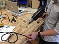 sliding shrink wrap over wiring then using a heat gun to seal it.
 -
 breakdown of prototype 2
 -
 prototype 2
 -
 side view of prototype 2


.JPG)
Week 5
editCode for the Arduino
/*
  Blink
  Turns on an LED on for one second, then off for one second, repeatedly.

  This example code is in the public domain.
 */
 // Pin 13 has an LED connected on most Arduino boards.
// give it a name:
int led = 13;
// the setup routine runs once when you press reset:
void setup() {
  // initialize the digital pin as an output.
  pinMode(led, OUTPUT);
}
// the loop routine runs over and over again forever:
void loop() {
  digitalWrite(led, HIGH);   // turn the LED on (HIGH is the voltage level)
  delay(1000);               // wait for a second
  digitalWrite(led, LOW);    // turn the LED off by making the voltage LOW
  delay(1000);               // wait for a second
}
Week 6
editThis week we designed our housing for the LEDs, battery and arduino(s) and are drawing the program in sketchup so that hopefully we may print by next week. We are currently still waiting on the LEDs we ordered and cannot set up or next prototype without these next multicolored LEDs.
<gallery> File:Specs for housing.JPG|Prototype twos dimensions for 3D printing